Ok i have been working on a 360 degree depth buffer for 2d lighting.
Currently this is prototyped on Dx windows on a win10 machine with vs2017
So far conceptually it works but i have one big problem i can’t think of how to tackle.
atan2 is used to find the x plotting position for mapping the depth, however this must be done on the vertex shader in order to warp the positions into place while the z part of the position calculates and passes the actual depth.
but
The problem with this is that atan2 returns a value that can be interpolated incorrectly across the 0 and 360 degree boundry line shown in the gif below for two connected vertices of a triangle improperly arggg.
For example say one vertex is at bering of -20 degrees and interpolates to the next vertex at 5 degrees. However this atan2 calculates the connected triangles next vertex at a bering of 345 degrees not -20. So it interpolates the x positions across the entire x space. Argggg…
I cant wrap positional coordinates like i can with texture coordinates using the sampler state. So that instead of 0 to 5 degrees and 345 to 360 degrees i end up filling the entire space from 5 to 345 degrees which is incorrect as seen in the gif.
The gif further below shows the problem in action.
Edit.
The following picture illustrates it.
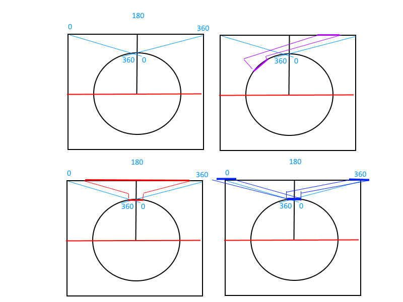
It seems like i will need to perform two draws to handle this but still clipping to get the blue lines is a problem on the vertex shader on either pass.
Is there a way to clip triangles from the vertex shader?
this line in the shader is the difficulty described above.
float unitx = (((atan2(direction.x, direction.y) / 3.14159265f) * 0.5f + 0.5f)) * ResolutionX;
VsOutputCalcSceneDepth CreateTestDepthMapVertexShader(VsInputCalcSceneDepth input)
{
    VsOutputCalcSceneDepth output;
    float4x4 wv = mul(World, View);

    float4 pos3d = mul(input.Position, wv);
    float3 light = mul(float4(WorldLightPosition, 1.0f), View);

    float2 direction = pos3d.xz - light.xz;
    pos3d.z = length(direction);
    pos3d.x = (((atan2(direction.x, direction.y) / 3.14159265f) * 0.5f + 0.5f)) * ResolutionX;

    output.Position3D = pos3d;
    output.Position = mul(pos3d, Projection);
    output.TexureCoordinateA = input.TexureCoordinateA;
    return output;
}
float4 CreateTestDepthMapPixelShader(VsOutputCalcSceneDepth input) : COLOR
{
    // HLSL atan2(x,y) == GLSL atan(y,x)

    float2 texcoords = input.TexureCoordinateA;
    float4 col = tex2D(TextureSamplerA, texcoords);

    col.rgb = 0.0f;
    col.r = FunctionPositionalDepthNormalized(input.Position3D.z, Projection); // if depth is high far we get a lot of red.
    col.g = texcoords.x * 0.15f;
    col.b = 1.0f - col.r; // if depth is low close we get a lot of blue
    col.a = 1.0f;
    return col;
}
if this were a texture i could set the sampler to wrap but this operation must be performed on the vertices.
Im thinking i need to somehow cut these off or clip them and draw twice. somehow but i can’t quite see how to do it ? Any thoughts on how to tackle this would be helpful.
In the shown gif in the the top area is the depth calculation visualization for the outlined image that is circling the center of the screen, which is were the light is. The blue and red color change of the image represents distance from the light.
So the 0 to 360 boundry is straight up from the red dot and that is were the interpolation problem between vertices is at.

Extra info.
I build a polygon outline of a image that extends into the z depth by generating it from a image.
Its drawn were the image would be. But i change the view direction to look down the y plane from the y height towards 0 y.
I do this so that im in essence placing my camera inside the plane looking down it in that flat space.
So in this way i have pulled the camera back to have a sandbox view of the work space.
In which i draw into for the depth against the light position, i calculated the x z - light x z direction and distance. The positional x value to be outputed by the vertex shader is then the assigned constrained resulting value of the atan2( direction ) as a unit value spanning the viewport width.
The viewport width height is passed into the shader as a global parameter. The positional z value is assigned the distance and the y value is untouched.
The depth stencil state is set to less than. So that all passed z positional values are checked against the z buffer check for the one dimensional line per light.
So both the views in the above gif are displayed for clarity to give a idea of what is going on.
Only the depth view would actually be used in practice, if i can get past this final hurdle.