Normal map lighting shader only gets brighter at 0,0

Good catch! Although that doesn’t fix the positioning of the light, that does help another problem I wasn’t looking at. Thank you!

Yeah you look to be right. The only problem now is that it starts to become unsynced with my mouse as I move away from 0,0.

(A bit laggy, was trying to keep it under the space req. for upload. But when its in the bottom right, you can see that its offset)

Any hints? :slight_smile:

Can you check if LightPos is 1,1 when the mouse is in the bottom right corner? It almost looks like that’s not the case.

1 Like

I just tested by normalizing lightPos before passing it to the shader(not sure how to check it otherwise), and you’re right. The bottom right is showing around 0.7, 0.7.

I had the back buffer height/width smaller then the actual image size; setting it to the same resolution as the image makes it show in the correct location.

What would be the best way to ensure the mouse coordinates track properly, even if the screen resolution/camera resolution is smaller then the image itself?

The problem is that LightPos and texCoord are using a different coordinate space. While LightPos is relative to the screen, texCoord is relative to the image. The subtraction (LightPos.xy - input.texCoord.xy) only makes sense if both are in the same coordinate space.

So you basically have two options. Change LightPos to image space, or, change texCoord to screenspace. Which option is better depends on whether you want the light to be relative to the image, or to the screen.

1.) Make LightPos use image space

LightPos.X = (mouseState.X - imageLeft) / imageWidth;
LightPos.Y = (mouseState.Y - imageTop) / imageHeight;

2.) use screenspace instead of texcoord

float2 screenCoord = (input.Position.xy / input.Position.w + 1) / 2;
screenCoord.y = 1-screenCoord.y;
1 Like

That makes sense!

When trying to use the second option, I get the following error:

Shader model ps_4_0_level_9_1 doesn’t allow reading from position semantics.

From my understanding, using Position requires shader model 5 or higher.(Unless I misunderstood) Is there any other way you can think of to use screenspace?

Yeah right, a common workaround for older shader models is to pass the position as a texcoord from the vertex to the pixel shader, that way you can access it. You probably don’t want to mess with the spritebatch vertex shader. Obviously you could just not use spritebatch, and just draw a quad using your own vertex shader. Fortunately you can also solve it in the pixel shader, with the help of some extra shader parameters.

This is how you can calculate the screen coordinates in the pixel shader

float2 screenCoord = TopLeftScreen + input.texCoord * SizeScreen;

TopLeftScreen and SizeScreen are float2 shader parameters. This is how you calculate them in code

Vector2 TopLeftScreen = ImageTopLeft / ScreenResolution;
Vector2 SizeScreen = ImageSize / ScreenResolution;

ImageTopLeft, ImageSize and ScreenResolution are all in pixels.

1 Like

That did it! Thanks a lot for your help, I appreciate it! :slight_smile:

Can this be used in 3d ? Or does it only work if the quad is in a specific orientation ?

How do you account for the quad itself being in a different orientation or a mesh for that matter ?

I never tried to do normal mapping anyone know of a good tutorial to do this in 3d ?

Yes, the normal mapping in this shader also works in 3D. If your mesh rotates, you just have to make sure to rotate the normals along with it. Also you would calculate LightDir differently.

For a directional sun light LightDir is just a constant shader parameter, and you can drop the Attenuation.

For a point light you can calculate LightDir and LightDistance from the light’s position and the world-position of the pixel, which you output from the vertex shader.

You probably also want to add specular highlights.

Lets say you have a cube you rotate it slightly. The front face part of the cubes normal map will be fine, But what about the cubes sides, or in the case of a mesh its arbitrary.

How do you account for the sides of the cube in order to bring them in line with just a surface normal.
The normal map needs to be rotated another 90 degrees in that case (in the case of a mesh its arbitrary) all you have to base a rotation on is a single vector.

So how do you get the side faces of a cubes triangle surface normal to rotate the normalMap’s corresponding normal or light vector into place?

Or is a second bi-normal or tangent vector a requirement per vertice as part of the vertex structure ?

I would guess you would build a rotation matrix from that on the pixel shader and then rotate the light?
That seems terribly expensive is that just how its done, or am i missing something ?

Im trying to read up on this but its a little unclear on what the basic idea is in the first place to handle the orientation of the plane on each triangle to equate it to the corresponding uv normal.

I keep seeing a formula for calculation of a tangent binormal normal TBN xyz im guessing its some shortcut but it is unclear as to how it all fits together and from were.

Edit… so i have been giving this a lot of thought.
I have found a ton of complicated solutions and it just occured to me that it seems there is a really straight forward way to do this. Im wondering if anything is wrong with my idea it seems simple.

Here it is in raw form along with a question.

//… ah
//…
// from the current position.xyz to the camera position we have a vector n0 = (camWorld.xyz - pos.xyz);
// from the triangle normal we have a passed in vector n1 that has been rotated into world space.
//
// the cross of (n0,n1) gives a axis.
// the dot of (n0,n1) gives a angle.
//
// (the result of the dot is a cosing meaning… result * result * pi = angleInRadians)
//
// i need to build a AxisAngle rotation quaternion or matrix and inverse rotate the normalMap vector by it.
// in the case of axis angle that amounts to putting a minus sign on the angle.
//…
// …
// that is all i need to do to bring it into the model space for the current uv normal.
// then dot the light normal by it to see the diffuse magnitude ect ect…
//
// This way there is no need to calculate a tangent or a bivector at all… ?
// so why is every solution doing it ?
// is there anything wrong with this logic ?

There’s (at least) two different types of normalmaps you can use, world-space and tangent-space.

With world-space normalmaps the normals are already pointing in the right direction. On the back-side of a cube the normals are pointing backwards, on the front side they point forward. This means that every face on the cube needs to be mapped uniquely, faces can’t share the same uv-space on the normalmap, unless the face orientation is the same. This can be a disadvantage (with tangent-space normals you could share uv space), but often you want a unique texture for all faces anyway, like when the cube has a scar on one side, but not the other.

World-space normalmaps are easier to program, and should be slightly more efficient, because you don’t need to rotate the normals, to align them with the surface of the mesh. Your mesh doesn’t even need to contain normals at all, if you do the lighting calculations in the pixel shader. You only need to rotate the normalmap normals with the main world rotation matrix of the object. That’s one matrix multiplication per pixel, not a big problem nowadays. If your mesh doesn’t need to rotate at all, this method will be very fast, because you can use the normals directly, without any extra rotations.

In tangent-space the normals in the normalmap are relative to the vertex normal and bi-normal they belong to. They need to be rotated first, to align them with the mesh surface orientation. That’s a little bit of extra work, but it allows you to share texture space between faces of different orientation, but maybe more important, it will work on deformable meshs, like skinned characters.
To build the surface-alignment rotation matrix you just combine the vertex normal, the vertex bi-normal, and their cross product into a float3x3. You can do that in the vertex shader, and pass the matrix on to the pixel shader. You probably want to incorporate the object rotation matrix as well, that way you only need one matrix multiplication in the pixel shader. It shouldn’t be too complicated, your mesh just needs to have those bi-normals.

Whichever method you use, you need to have the right type of normalmap. Tangent-space normalmaps are usually mostly purple, because the normals tend to face in a forward direction only. World-space normalmaps tend to use a larger color space, as the normals can point in all directions.

Wouldn’t that make the lighting dependent on the camera position?

Another question that popped up. I’m trying to implement multiple light sources now, and running into a bit of trouble.

The result of this running is that I see one light source(my mouse), but the second light source doesn’t show up.

Texture2D SpriteTexture;
Texture2D NormalTexture;

sampler2D SpriteSampler = sampler_state
{
    Texture = <SpriteTexture>;
};
sampler2D NormalSampler = sampler_state
{
    Texture = <NormalTexture>;
};

const static int maxLights = 2;
float2 Resolution;
float3 LightPos[maxLights];
float4 LightColor;
float4 AmbientColor;
float3 Falloff;
float2 TopLeftScreen;
float2 ScreenSize;


struct VertexShaderOutput
{
    float4 Position : SV_Position;
    float4 color : COLOR0;
    float2 texCoord : TEXCOORD0;
};


float4 MainPS(VertexShaderOutput input) : COLOR
{
    float3 FinalColor = float3(0.0, 0.0, 0.0);
    float2 screenCoord = TopLeftScreen + input.texCoord * ScreenSize;
    float4 DiffuseColor = tex2D(SpriteSampler, screenCoord);
    float3 NormalMap = tex2D(NormalSampler, screenCoord).rgb;


    [loop]
    for (int i = 0; i < maxLights ; i++)
    {
        float3 LightDir = float3(LightPos[i].xy - screenCoord.xy, LightPos[i].z);
        LightDir.x *= Resolution.x / Resolution.y;
        float D = length(LightDir);

        float3 N = normalize(NormalMap * 2.0 - 1.0);
        float3 L = normalize(LightDir);

        float3 Diffuse = (LightColor.rgb * LightColor.a) * max(dot(N, L), 0.0);
        float3 Ambient = AmbientColor.rgb * AmbientColor.a;
            
        float Attenuation = 1.0 / (Falloff.x + (Falloff.y*D) + (Falloff.z*D*D));

        float3 Intensity = Ambient + Diffuse * Attenuation;
        float3 TempColor = DiffuseColor.rgb * Intensity;
        FinalColor += TempColor;
    }


    return input.color *  float4(FinalColor, DiffuseColor.a);

}

technique SpriteDrawing
{
    pass P0
    {
        PixelShader = compile PS_SHADERMODEL MainPS();
    }
};

I’m just passing an array of Vector2 into LightPos. One is the mouse coordinates, the other is a random location on screen(0.187, 0.333, 0.08)

To build the surface-alignment rotation matrix you just combine the
vertex normal, the vertex bi-normal, and their cross product into a
float3x3.

Well the idea was to not to have to send in the extra tangent data per vertex i really don’t like that idea.
That’s extra data and you need a rotation plus you have to calculate it on the mesh.

from the current position.xyz to the camera position we have a vector n0 = (camWorld.xyz - pos.xyz);

Wouldn’t that make the lighting dependent on the camera position?

Oh ya your right. Maybe the cameras.Backwards instead i think.

Still the idea would require building a axis angle function in the shader.
I think im going to make a quick test cpu side and see if this would work.

Pass the light in as world space positions.
like
lightPosition = new Vector3(0f,0f, 1f);

you could add or subrtract to the vector elements with some keyboard keys.
lightoffset = new Vector3(0f,0f,0f);

            if (Keyboard.GetState().IsKeyDown(Keys.W))
                lightoffset.Y += .005f;
            if (Keyboard.GetState().IsKeyDown(Keys.S))
                lightoffset.Y += -.005f;
            if (Keyboard.GetState().IsKeyDown(Keys.A))
                lightoffset.X += .01f;
            if (Keyboard.GetState().IsKeyDown(Keys.D))
                lightoffset.X += -.01f;
            if (Keyboard.GetState().IsKeyDown(Keys.Q))
                lightoffset.Z += .005f;
            if (Keyboard.GetState().IsKeyDown(Keys.Z))
                lightoffset.Z += -.005f;

// then move all the lights before passing them to the shader.
lightPositionToPassToShader = lightPosition + lightoffset;

You could change that lighting formula if you dont like it.
//float Attenuation = 1.0 / (Falloff.x + (Falloff.yD) + (Falloff.zD*D));
float Attenuation = 1.0;

1 Like

Humm this seems to work by the numbers.

here is the test and the output.

    void test()
    {
        var mn = new Vector3(0, 0, 1); // the map normal
        var vn = new Vector3(1, 0, 0); // the vertice normal
        var camPos = Vector3.Zero;
        var camForward = Vector3.Normalize(new Vector3(0, 0, -1));
        var camMat = Matrix.CreateWorld(camPos, camForward, Vector3.Up);
        var viewMat = Matrix.CreateLookAt(camMat.Translation, camMat.Forward + camMat.Translation, camMat.Up);
        var worldView = camMat * viewMat;
        var w_vn = Vector3.Transform(vn, worldView);
        // heres were the formula comes in the above is standard stuff.
        var w_mn = Vector3.Transform(mn, worldView);
        var n0 = -camForward;
        var n1 = w_vn;
        var axis = Vector3.Cross(n0, n1);
        var ncos = 1f - Vector3.Dot(n0, n1);
        var angle = ncos * ncos * (3.14159265f *0.5f);
        var aaRotMat = Matrix.CreateFromAxisAngle(axis, angle);
        var t_vn = Vector3.Transform(w_vn, aaRotMat);
        var t_mn = Vector3.Transform(w_mn, aaRotMat);
        Console.WriteLine(
            " so for a tangent space mapped normal that is originally encoded facing " + mn +
            " on a triangle facing " + vn + 
            " we find by formula that transformed the mapped normal on that face will be " + t_mn
            );
    }

Heres the output…

so for a tangent space mapped normal that is originally encoded facing {X:0 Y:0 Z:1} on a triangle facing {X:1 Y:0 Z:0} we find by formula that transformed the mapped normal on that face will be {X:1 Y:0 Z:-4.371139E-08}

the z is basically zero as its e-08

So unless im not seeing something this appears to work aside from handedness which could be solved with quaternions…

  1. this can be done on the shader,
  2. it appears that no tangent or bitangent is needed.
    i mean it looks like it worked.

I don’t know about the handedness that would probably be off im not sure it would matter though.
i guess it could be done with quaternions on the shader i dunno i don’t use them hardly ever.

Anyone have a axisangle function for a shader ?

I thought the content pipeline already supports generating tangents, you shouldn’t have to calculate them yourself. If you don’t like the extra data per vertex, you should be a big fan of the world-space normal mapping I described (if you can live with it’s limitations). Not only do you not need the extra tangent, you can even get rid of the standard vertex normal. Not sure why world-space normals aren’t more popular than they seem to be, tangent-space seems to rule. In many cases tangent-space doesn’t seem to offer any benefits, in which case world-space should just be the simpler and more efficient method, maybe I’m missing something.

As for the extra rotation, no matter how you spin it, if you use tangent-space normalmaps, you will need to do some math on those normals, before you can use them. The matrix multiplication for the rotation equates to 3 extra dot products in the pixel shader, plus the assembly of this matrix in the vertex shader, which is also very simple. I doubt that any method you can come up with will be much more efficient than that, without having some shortcomings. That’s probably why everyone is using that method, it’s efficient at what it does.

same problem as before, only now the lighting is dependent on the camera’s orientation, instead of it’s position. You want the lighting - at least the diffuse part - to be completely independent from the camera. I don’t think replacing the per-vertex tangents with any constant vector will work well, without some kind of shortcomings.

It’s like trying to orient a plane to face in a certain direction. You can do that by just specifying a normal for the plane, but without also specifying a tangent, the plane can still freely spin around that normal, so there’s an infinite number of possible solutions. The tangent makes sure there is only one possible solution, so it fixes this spin angle. For normalmapping fixing the angle matters, because it tells you what it means for a normal (from the normalmap) to face in the X or Y direction. The standard vertex normal just tells you what it means to face along the Z-axis. That’s the best way I can explain it, but I guess it’s still confusing, sorry.

as I said before, for a z-only normal like you are using {X:0 Y:0 Z:1} you don’t need the tangent, it’s when you have a normal like {X:1 Y:0 Z:0} where tangents become important. It looks like you are just hardcoding the tangent for all triangles, but every triangle can be different, that’s why you need this information per vertex.

The shader code looks like the 2nd light should show up. Is maybe the LightPos[maxLights] array not filled up properly. I’m wondering if it’s only the first light that’s working, and the 2nd one is always missing. You can check that by just swapping the lights, make your mouse light the 2nd light, and see if it still shows. If it still shows, then you know the array gets filled properly and the problem is somewhere else.

1 Like

I thought the content pipeline already supports generating tangents, you shouldn’t have to calculate them yourself.

Im generating a mesh using custom vertex data, so i would have to generate the tangents myself.
Generating world tangents like that isn’t trivial as you couldn’t simply change out textures they would have to be specifically made for a model. Which for generic objects would be limiting walls floors ect
i want to change out different textures and normal maps…

The matrix multiplication for the rotation equates to 3 extra dot products in the pixel shader

You mean if you put tangents into the vertices ?

The tangent makes sure there is only one possible solution, so it fixes
this spin angle.

The standard vertex normal just tells you what it
means to face along the Z-axis.

Im not quite convinced this wont work.

// with spin it ends up still aligned.
var mn = Vector3.Normalize(new Vector3(0, .2f, 1)); // the map normal
var camMat = Matrix.CreateWorld(camPos, camForward, Vector3.Left);
//…
var w_mn = Vector3.Transform(mn, worldView);
//…
var t_mn = Vector3.Transform(w_mn, aaRotMat);

so for a tangent space mapped normal that is originally encoded facing {X:0 Y:0.1961161 Z:0.9805807}
on a triangle facing {X:1 Y:0 Z:0}
we find by formula that transformed the mapped normal on that face will be {X:0.9805807 Y:0.1961161 Z:-4.286254E-08}

It looks like the tangent space is mapping to the plane space of the triangle correctly even if its offcenter and the camera has z axis rotation as well. Ill probably build the tanents into vertexs if this worked someone woulda done it by now.
I cant run the real test anyways or id just show some pics and see how it goes. But im getting a brutal exception trying to get this test to run on the shader.

As long as the textures are using the same uv-mapping you should be able to swap textures without also changing the tangents.

Yes, in the pixelshader you only need one mul(float3, float3x3)

You are making the assumption here that an upwards pointing normal should still end up pointing upwards when mapped onto a side-facing triangle. That might be fine for your particular case, but it’s not true in general. Just flip the uv-mapping on this side-facing triangle upside down, now you want the normal to point downwards instead of up.

.

Ya when i got the shader working the orientations were all screwed up.
Guess ill just add tangents to the mesh and try to do it the regular way.

Dont like having the extra data in there but oh well.
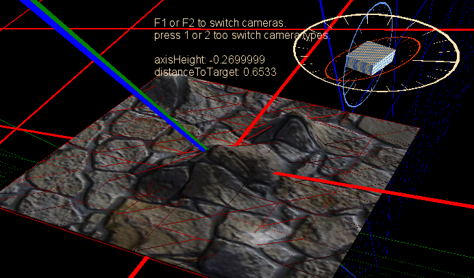
Edit:

That is nice, one of eric metays brick pictures from his shared images site.

Texture2D SpriteTexture;
Texture2D NormalTexture;

sampler2D SpriteSampler = sampler_state
{
	Texture = <SpriteTexture>;
};
sampler2D NormalSampler = sampler_state
{
	Texture = <NormalTexture>;
};

//___________________________________

struct VsNormMapInput
{
	float4 Position : POSITION0;
	float3 Normal : NORMAL0;
	float2 TexCoord : TEXCOORD0;
	float3 Tangent : NORMAL1;
};

struct VsNormMapOutput
{
	float4 Position : SV_POSITION;
	float4 PositionWorld : TEXCOORD4;
	float2 TexCoord : TEXCOORD0;
	float3 Normal: TEXCOORD1;
	float3 Tangent : TEXCOORD2;
};

VsNormMapOutput VsNormMap(VsNormMapInput input)
{
	VsNormMapOutput output;
	float4x4 vp = mul(View, Projection);
	float4x4 wvp = mul(World, vp);
	output.Position = mul(input.Position , wvp);
	output.PositionWorld = input.Position;
	output.Normal = input.Normal;
	output.Tangent = input.Tangent;
	output.TexCoord = input.TexCoord;
	return output;
}

float4 PsNormMap(VsNormMapOutput input) : COLOR0
{
	float4 DiffuseColor = tex2D(SpriteSampler, input.TexCoord);
	float3 NormalMap = tex2D(NormalSampler, input.TexCoord).rgb;
	// flips the y. the program i used fliped the green.
	NormalMap.g = 1.0f - NormalMap.g;
	NormalMap = normalize(NormalMap * 2.0 - 1.0);
	float3 normal = mul(input.Normal, World);
	float3 tangent = mul(input.Tangent, World);
	float3x3 mat;
	mat[0] = cross(normal, tangent); // right
	mat[1] = tangent; // up
	mat[2] = normal; // forward
	NormalMap = mul(NormalMap, mat);
	float D = length(LightPos - input.PositionWorld);
	float3 N = NormalMap;
	float3 L = normalize( -LightDir);
	float3 Diffuse = LightColor.rgb * max(dot(N, L), 0.0f);
	float3 Ambient = AmbientColor.rgb;
	float AmbientStrength = 0.1f;
	float3 FinalColor = DiffuseColor.rgb * ( (Ambient * (AmbientStrength) ) + (Diffuse * (1.0f - AmbientStrength))  );
	return float4(FinalColor, 1.0f);
}

technique MapDrawing
{
	pass
	{
		VertexShader = compile VS_SHADERMODEL VsNormMap();
		PixelShader = compile PS_SHADERMODEL PsNormMap();
	}
}

Here are some shader side quaternions and axis angle matrix functions.

// Quaternions mostly copy paste, couple i made none are tested.

// struct
struct Spatial { float4 pos, rot; };
//rotate vector 
float3 qrot(float4 q, float3 v) { return v + 2.0*cross(q.xyz, cross(q.xyz, v) + q.w*v); }
//rotate vector (alternative) 
float3 qrot_2(float4 q, float3 v) { return v * (q.w*q.w - dot(q.xyz, q.xyz)) + 2.0*q.xyz*dot(q.xyz, v) + 2.0*q.w*cross(q.xyz, v); }
//combine quaternions 
float4 qmul(float4 a, float4 b) { return float4(cross(a.xyz, b.xyz) + a.xyz*b.w + b.xyz*a.w, a.w*b.w - dot(a.xyz, b.xyz)); }
//inverse quaternion 
float4 qinv(float4 q) { return float4(-q.xyz, q.w); }
//transform by Spatial forward 
float3 trans_for(float3 v, Spatial s) { return qrot(s.rot, v*s.pos.w) + s.pos.xyz; }
//transform by Spatial inverse 
float3 trans_inv(float3 v, Spatial s) { return qrot(float4(-s.rot.xyz, s.rot.w), (v - s.pos.xyz) / s.pos.w); }
//perspective project 
float4 get_projection(float3 v, float4 pr) { return float4(v.xy * pr.xy, v.z*pr.z + pr.w, -v.z); }
//quaternion axis angle hopefully i did this right.
float4 axis_angle(float4 axis, float angle) { float ha = angle * 0.5f; float s = sin(ha); float c = cos(ha); return float4(axis.x* s, axis.y* s, axis.z* s, c); }

// Matrix this one i just translated straight from monogame.
float4x4 CreateFromAxisAngle(float3 axis, float angle)
{
    float x = axis.x;
    float y = axis.y;
    float z = axis.z;
    float s = sin(angle);
    float c = cos(angle);
    float xx = x * x;
    float yy = y * y;
    float zz = z * z;
    float nxy = x * y;
    float nxz = x * z;
    float nyz = y * z;
    float4x4 result;
    result._m00 = xx + (c * (1.0f - xx));
    result._m01 = (nxy - (c * nxy)) + (s * z);
    result._m02 = (nxz - (c * nxz)) - (s * y);
    result._m03 = 0.0f;
    result._m10 = (nxy - (c * nxy)) - (s * z);
    result._m11 = yy + (c * (1.0f - yy));
    result._m12 = (nyz - (c * nyz)) + (s * x);
    result._m13 = 0.0f;
    result._m20 = (nxz - (c * nxz)) + (s * y);
    result._m21 = (nyz - (c * nyz)) - (s * x);
    result._m22 = zz + (c * (1.0f - zz));
    result._m23 = 0.0f;
    result._m30 = 0.0f;
    result._m31 = 0.0f;
    result._m32 = 0.0f;
    result._m33 = 1.0f;
    return result;
}

I figured it out. The second Vector3 I was sending had z set to 0.8f, where-in it had to be closer to 0.08f…a bit embarrassing!

I really appreciate you time and assistance though! :slight_smile: