Point lights and shadow mapping

I was cleaning up some of my lighting and shadow mapping code when I noticed that shadows are not being generated when using point lights.

Specifically the reason seems to be generating the view for the light i.e.

        Matrix lightView = Matrix.CreateLookAt(light.Position, light.Position + light.Direction, Vector3.Up);

Since point lights have no direction, the above code generates a view with NaN (since position and target are the same), and this breaks the shadow mapping.

I googled to see how this is handled for point lights, but have not been able to find anything on this.

Could someone please explain how I could get shadow mapping working with point lights?

Whilst I am on the topic of lights and shadows… when creating a perspective field of view for point and spot lights, what FoV am I supposed to be using for each type? Do I use the cone angle for the spot light? I have seen some samples / articles used a fixed FoV, whilst one of the books I have uses the angle from the spot light.

Similarly, for the point lights (once I figure out how to get that working), what angle should the FoV be?

Thanks!

Yeah, you should probably include a perspective matrix for point and spot lights. For spot lights using the cone angle as your FOV sounds good. For point lights it depends on where you want it to cast shadows.

Technically a point light can cast a shadow all around. This is impossible with a single shadow map. You would need multiple shadow maps, ideally a shadow cube.

If you can limit the shadows to a specific area however, just point your light direction towards the center of this area, and make your FOV as large as it needs to be to cover the area. You have to stay below 180 degrees, because a perspective matrix can’t go beyond that.

1 Like

Just to be clear im reffering to point lights here like a lamp and not spot lights like a flash light.

Point lights do have a direction you just calculate it on the shader.

What you pass to the shader is its position.

lightDirection = normalize( input.position - lightPosition );

That is typically done in the pixel shader because the direction from the light to the pixel is needed on a pixel by pixel basis for comparision against the interpolated surface normal of pixel for the current triangle.
A sufficiently distant light positions to any pixel is basically omni directional which is why many shaders just take a direction to represent a very distant light source like the sun.

The steps broken down further are as so…

Typically you rotate your pixel position in the vertex shader then set that to another variable.

float3 pos = mul(input.position, World);
output.Position3D = pos.xyz;

One that wont be set to homogenous space when passed to the pixel shader.

struct VsOutputSkinnedQuad
{
float4 Position : SV_Position;
float4 Color : Color0;
float2 TexureCoordinateA : TEXCOORD0;
float3 Position3D : TEXCOORD1;
float3 Normal3D : TEXCOORD2;
//float3 Tangent3D : NORMAL1;
//float3 BiTangent3D : NORMAL2;
};

Also you pass the light position at the start of your draw then do the first calculation shown typically in the pixel shader but you could do a cheap version possibly less accurate on the vertex shader.

The normal of your model is doted against that to determine if the pixel is backface or not to the light as well as the magnitude of diffuse intensity. This ranges from zero to 1 (negatives need to be clamped or saturated);

The below are common shader calculations the light is represented as L

float3 N = input.Normal3D;
float3 L = normalize(WorldLightPosition - input.Position3D);
float3 C = normalize(CameraPosition - input.Position3D); 
float diffuse = saturate(dot(N, L)) * DiffuseAmt; // dot(N, L) is the important part it is the magnitude of the angle between surface normal to the surfaceToLight normal it ranges from 0 to 1 negative vals are NA.
float reflectionTheta = dot(C, reflect(-L, N)); // this is the magnitude of the reflection to your eye ranges from 0 to 1 as negatives should be occluded.
float IsFrontFaceToLight = sign(saturate(dot(L, N))); // 1 is Frontface 0 is Backface  the light to surface normal relation.
float4 texelColor = tex2D(TextureSamplerA, input.TexureCoordinateA) * input.Color;

The pixel position distance to the lightPosition determines the depth for the shadow as well.

Using a shadow cube has some pitfalls. If that is the route you are going…

Then i highly suggest you read the below issue there is at least 2 or 3 gotchas when using a render target cube…

I still have a runnable test project at the bottom of this issue as well.
This is from when i was testing and it has a single point light in the shader though im not going to claim this is the best or even a good way to do it. It was done as a proof of concept test.

Markus and pumpkin were a lot of help getting that to work.

Here is a pic from a later test that shows the point light in teal as a cube.
The cube itself was used to draw the shadow map onto for debuging so you can see little dark areas on it which is actually the depth map monochrome then with teal shading to represent the most distant depths beyond some set limit.

Thanks for the pointers. I will play around with it a bit more and see what I can come up with.

I did point light shadows with two render targets, one for each hemisphere. But there’s a trick to projecting the triangles and samples onto the texture, since, yeah, matrices can’t help you there. Instead, if I remember correctly, you have to write a custom vertex shader to place the vertices in their proper predictable spots. Off hand, I forget the equations - they were very simple once you work them out, but it involved something about the derivative of a paraboloid, as if projecting onto a convex mirror, or something like that. The shadow maps (again, one for each hemisphere) end up looking like a “fisheye lens”. I can dig up the exact algorithm if you wish.

Ya id like to see it for sure. Does it handle the edges correctly were the two lens meet?

The bad thing about render target cubes is of course they are cubes … with six faces.
So that can get expensive fast.

Valid concern, but yes, I think it was just fine.
Give me a little bit, as the next couple days will be busy, but I’ll draw up an explanation when I get a chance.

No rush im not doing anything related to that atm anyways.
Just interested.

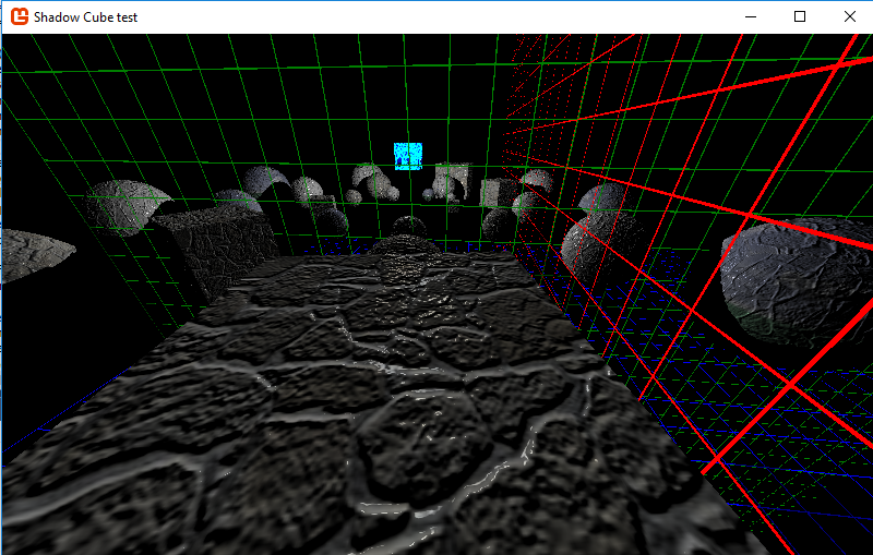
Here’s an explanation of how I did it. As I said, this will require two shadow depth maps (the likes of which I presume you used for your other light sources), one for each hemisphere.

Please excuse the crudity of this model; I illustrated it hastily in Paint.

Furthermore, for simplicity, I’m demonstrating this in 2D, but it’s easily transferable to 3D analogously.

The process for creating each hemisphere’s depth map differs from that of other light types primarily in that we have to project the vertices onto the hemisphere in a predictable way such that we can later sample the corresponding points.

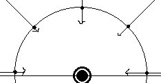
In this illustration, see that the incoming rays (the depth info that we’re trying to record) is going to the point light, but we’re going to imagine writing them onto the surrounding hemisphere.

Problem is, obviously, that we don’t have a hemisphere on which to write; we have square render targets. So we need to transform the incoming position data onto a flat surface.

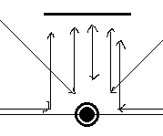
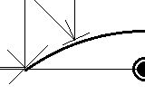
The way that we can project omnidirectional rays into parallel ones, as illustrated, is through the use of a parabolic mirror. Or, at least, that’s how we’re going to imagine it.

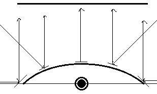
If I can figure out where the incoming rays intersect this parabola, I can place it onto the render target accordingly. For example, that leftmost ray will strike the leftmost point of the parabola (which is angled 45 degrees), and be reflected straight up onto the left edge of the render surface.

But in order to know where the ray intersects the parabola, I need to know its equation. As stated above, the left edge, coordinates (-1, 0), should be angled 45 degrees, or have a slope of 1. The right edge, coordinates (1, 0), should have a slope of -1, and the exact centre (x=0) should have a slope of 0. Therefore, dz/dx = -x.

We could then solve the exact equation of the parabola, but as it turns out, this is all we need. Just recognise, however, that that differential equation above is the slope of the tangent line, whereas the normal - that which is perpendicular to the tangent - is what is going to help us with the reflection. Therefore, we need to consider the “opposite reciprocal”: dx/dz = x.

To compute the normal of reflection, we basically just have to average the unit displacement - the normalised vector between the point light and any vertex that we’re projecting - and the direction to which it’s being reflected.

float3 dd = input.Position - LightPosition;
float3 normal = normalize(normalize(dd) + float3(0, 0, 1)); // or whatever

With this normal vector’s ratio of Δx to Δz and the equation above, we can then identify the x coordinate at which to relocate it, which, again, is simply that aforementioned ratio.

Then, repeat this same logic for the y coordinate.

float distance = length(dd) / MAX_DEPTH;
output.Position = float3(normal.x/normal.z, normal.y/normal.z, distance);

So it turns out, that lengthy explanation aside, it’s actually quite a simple solution. Just gotta do this once for the positive z direction, and again for the negative z direction.

When it comes to sampling the depth from this depth map, just repeat the process: find the direction to the vertex in question, average it with the appropriate z direction, and the resulting Δx/Δz and Δy/Δz ratios will give you the point to sample on the appropriate hemisphere map, depending on the sign of Δz. (Just don’t forget to transform those results into texture coordinates!)

1 Like

That sounds to easy.

the left edge, coordinates (-1, 0), should be angled 45 degrees, or have a slope of 1.
The right edge, coordinates (1, 0), should have a slope of -1

You said the left edge should be angled 45 degrees. You mean 90 degrees to the left or right though ?
Because the camera would need to be set to 180 degrees fov for the rendertarget depth render right?

Im guessing the two planes for the rendertargets stay stationary perpendicular to the system z axis.
3)
This calculation is done on the pixel shader in world space the same way i was passing my Position3D and Normal3D right ?

  1. These figures are regarding the imaginary parabolic mirror, not the actual camera. This is so as to explain the derivation of the algorithm. Note the angle of the parabola at the left and right extremes in my third illustration above. The camera, on the other hand, has no angular field of view in this algorithm; you can imagine it looking straight along those parallel rays towards the supposed mirror.

  2. Yes, for ease, it’s best to keep the Z axis fixed.

  3. Yes, the incoming coordinates in question (the vertex position and light position) are in world space. However, the lines of code given above are going to be in the vertex shader (since it involves relocating them), not the pixel shader. The pixel shader is basically just going to write the depth as a colour - in my example, I stuck it in the vertices’ Z component, so the pixel shader would basically just say

    return float4((float3)input.Position.z, 1);