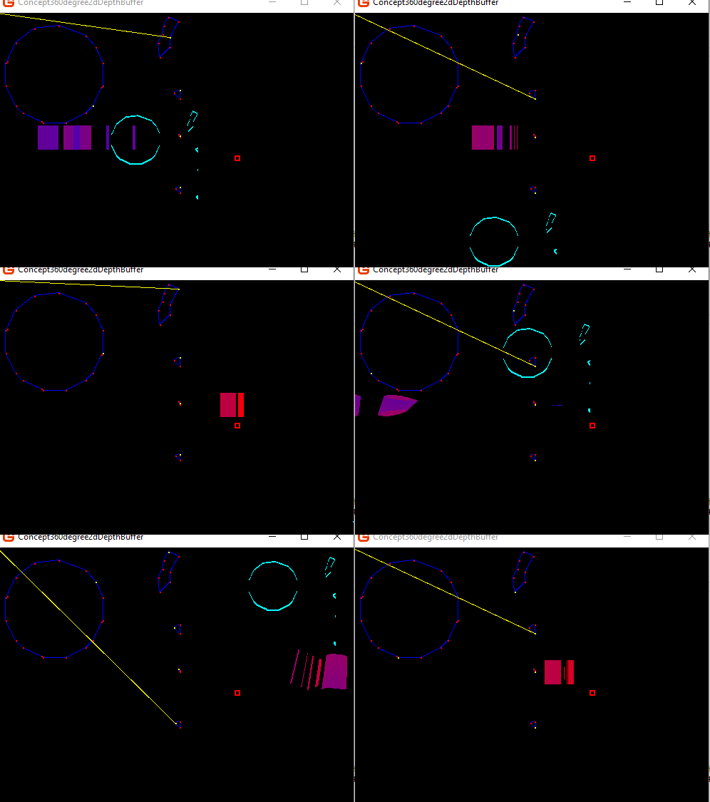
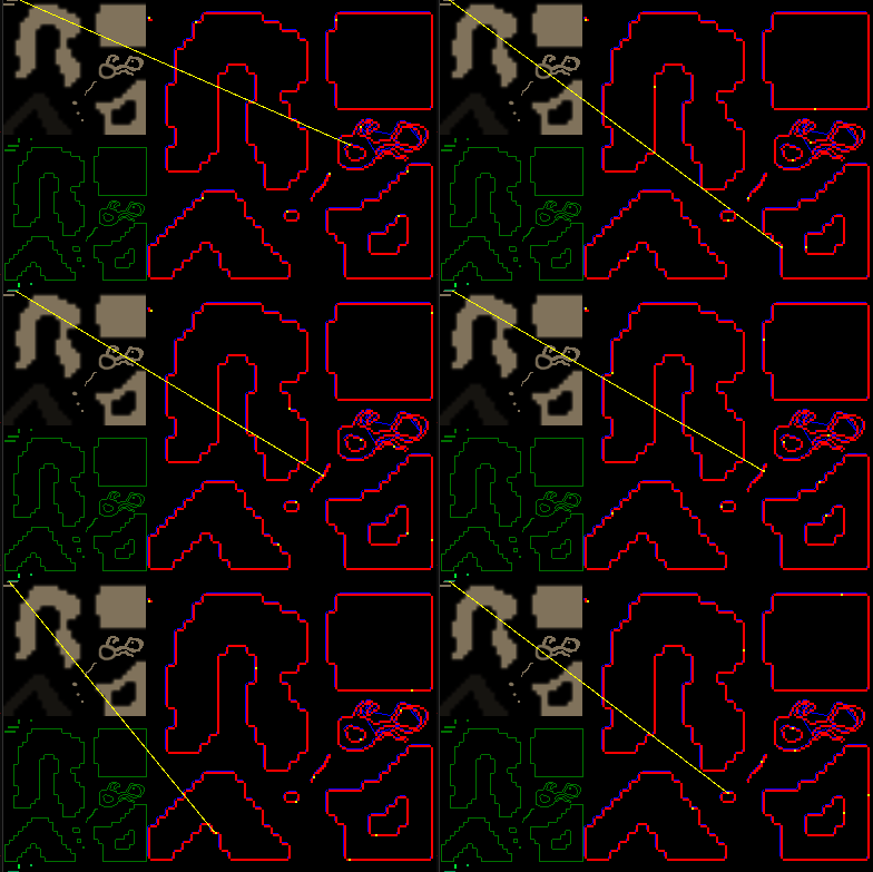
Ok i just wanted to show this off a bit more i got a proof of concept test.
Doing this was hard as hell to get a single pass 360 degree depth buffer algorithm made.
This isn’t completely done and i was sick for like a week so it took even longer.
But the hardest part is done.
The red square represents a light source.
The blue circle is a refined version of the previous algorithim.
The teal circle spining around represents a image or the polygonal outline of the image under motion in 2d this is just to make things clearer.
The redish blueish bars moving from side to side represent the depth to the image in 2d as seen from the light. Red means it is farther Blue closer.
So basically this is a single pass 360 degree depth buffer only one pixel line is needed per light. Later the scene when drawn again, can use the depth buffer for true 2d shadow or lighting. As each light has its own 360 degree depth map to everything else.

I sort of wish i didn’t need to generate a outline of a image to do it, but depth biasing wont work in this particular case. And i wanted to be able to have all the lights run in a single pass. Still have to add that in which maybe a little more work but probably not as difficult.
So it took me about 8 test class tries 8 shaders and i dunno how many thousands of lines i typed and tons of extra tests included primarily to get this.
    // simultaneously non intersecting.
    wrldPos.x = (((atan2(worldDirection.x, worldDirection.y) / 3.14159265f))) * ResolutionX;
    // simultaneously intersecting right vertice.
    wrldPos.x = wrldPos.x - (ResolutionX * 2.0f * isUp * isRight * isIntersecting);
    // simultaneously intersecting left vertice.
    wrldPos.x = wrldPos.x - (ResolutionX * 2.0f * isUp * isLeft * isIntersecting);
Well really this very raw vertex shader code, it can be trimmed down more.
    VsOutputCalcSceneDepth2D output;

    float4 wrldlight = float4(WorldLightPosition, 1.0f);
    float4 wrldPos2 = mul(input.Position, World);
    float4 wrldPosPartner = mul(float4(input.PositionPartner, 1.0f), World);
    float isIntersecting = 1.0f - saturate(sign((wrldPos2.x - wrldlight.x) * (wrldPosPartner.x - wrldlight.x)));
    float isUp = saturate(sign(wrldlight.y - wrldPos2.y));
    float isRight = saturate(sign(wrldPos2.x - wrldPosPartner.x));
    float isLeft = (1.0f - isRight);
    float2 worldDirection = wrldPos2.xy - wrldlight.xy;
    float dist = distance(wrldPos2.xy, wrldlight.xy);
    //
    float4 wrldPos;
    wrldPos.y = abs(wrldPos2.z); // +200.0f;
    wrldPos.z = dist;
    wrldPos.w = 1.0f;

    // simultaneously non intersecting.
    wrldPos.x = (((atan2(worldDirection.x, worldDirection.y) / 3.14159265f))) * ResolutionX;
    // simultaneously intersecting right vertice.
    wrldPos.x = wrldPos.x - (ResolutionX * 2.0f * isUp * isRight * isIntersecting);
    // simultaneously intersecting left vertice.
    wrldPos.x = wrldPos.x - (ResolutionX * 2.0f * isUp * isLeft * isIntersecting);

    //
    wrldPos = float4(wrldPos.x / (ResolutionX), wrldPos.y / (ResolutionY), wrldPos.z / (ResolutionY), 1.0f);
    output.Position = wrldPos;
    output.Position3D = wrldPos;
The orthographic camera when used to draw the image polygons is placed in the screen plane at the bottom 0, viewport.Height, 0, faceing 0,0,0 then the polygons are draw exactly were the image destination rectangle would be,
 .
.