Hi @markus,
I believe that’s only true if you look at spherical symmetric surfaces. Also, it depends a bit on the radiation characteristics (e.g., Lambertian). But you are of course right about the 1/z rule. I’ll have to think about it a bit.
Hi @AcidFaucent,
I must confess I have not yet heard about the hemicube method, but will check it out asap. Thanks!
What I meant was to include distance for every rendered pixel, not a constant distance value. That should allow you to calculate the real world size for every pixel in your map individually. If you also need the surface normal, you can include that in your rendering as well.
To me it still seems like you wouldn’t need the real world size of the pixels, but maybe I’m missing something, I’m really not a heat-transfer expert.
Hi @markus,
You were right about the 1/r^2 dependency. The source of my confusion was that I have done something very similar for the sun already, which is basically a point source at infinity. Hence, in this case, I can ignore the distance, the incoming ray density is constant and all rays parallel.
In the case of a radiating surface I will indeed need the surface normal and the depth information for each pixel to compute the radiative heat transfer between individual elements. I am going to check our the hemicube algorithm proposed by @AcidFaucent for that.
I am going to check our the hemicube
Hemicube and fisheye are both for integration on a surface. It sounds more like you’re after an approximate where your object is just an arbitrary point/cube (I assume by element you mean a whole object and not a sample point on an object), in which case you probably want to be using a GBuffer cubemap and sampling that.
Although it’s about light, thermal radiation is mostly the same (it just reacts with participating media [air] and in a multipass for convergence it has a loss - which you may not care about). Most exposure related things can be found in the same fashion just working with different values (kelvin instead of lumen, etc) and different tweaks (static absorption is strongest at perpendicular angles that along the vector to ground and never zero, etc).
The old Hugo Elias article is one of the best sources:
The Witness blog covered a fair bit on radiation: Hemicube Rendering and Integration – The Witness as well as different projections.
Advanced Global Illumination 2006 and Practical Global Illumination with Irradiance Caching are good, but unless you’re nuts about the subject only worth checking out from a library.
If you get lost, ask and I can toss a bunch of C++ code I use for doing this stuff (determining hemicube coordinates, multiplier map construction, and summation).
Wide but still less than 180 degree views tend to work fine though, something like an 18% inaccuracy compared to a hemicube sampling IIRC which is usually okay for anything non-life/ops-critical.
1 Like
Hi @AcidFaucent,
You are right, an approximate solution is what I am after. In this particular case, radiative heat transfer between individual components inside the satellite is not a dominant effect. Furthermore, there is no participating medium, since the inside of the satellite is going to be in vacuum.
Thanks for the sources, I will check them out and start working on a solution afterward. If it turns out that it’s too complex for what I have in mind and I have trouble integrating it, I would like to come back to your offer of some C++ snippets.
May I ask where you got the 18 % inaccuracy from? Under what circumstances has this been the case?
May I ask where you got the 18% inaccuracy from? Under what circumstances has this been the case?
From comparing running both a 150deg fisheye and a hemicube (128x128 face resolution) IIRC and the scenario was for light in lux, which is sensible most of the outer degrees are low contribution, and the two have different densities (hemicube is densest per-solid angle at increments of 45deg off-center [cube corners]), as well as the warping of geometry that isn’t highly tessellated when using a high-FOV.
Have you considered the technique involving two parabolic surfaces? I’m not sure what it’s name is - I don’t think it’s the hemi cubes you mentioned - but I’ve used it to circumvent the need for cube maps for omnidirectional point light shadow casting, so it might be relevant to your intent.
Dual-parabaloid. http://cdn.imgtec.com/sdk-documentation/Dual+Paraboloid+Environment+Mapping.Whitepaper.pdf
It works, just have to watch out with poorly tessellated geometry.
Yeah. That is what stumped me for the longest time.
Thanks again, @AcidFaucent, for the Hugo Elias source. Very well written! I have now integrated the hemicube approach and it seems to work:

The lefthand side shows the scene with the red dots displaying the five camera pointing directions with the camera sitting in the center point. The righthand side is the resulting hemicube texture of the resulting images with the transfer map applied.
The only thing I am lacking now is a fast way to sum over the (float) values of the right image. GetData<Color>() would do the job but is incredibly slow (frame rate drop by a factor of 10 - 100 depending on the resolution of the texture).
Maybe I could use a custom sprite effect to sum over the pixels and then render the result into a new texture. Any ideas are welcome.
If you create a render target with the mipmap flag enabled, it should automatically downsample to a single pixel on the smallest mipmap level. The pixel’s value will be the average of the entire texture. Multiplying this one pixel by the total pixel count should get you the sum.
I never tried that with cube textures, it should work the same though. You just have to do it for all 6 cube faces.
Thanks, that’s a great idea! Can I somehow access the generated mipmap outside of the shader?
If you want to access the mipmap from the CPU you can just specify the mipmap level in the GetData call, or do you mean something different?
Hi @markus,
That’s what I was looking for, thanks. I compared both methods - they yield the same results - and interestingly (but not intuitively), the mipmap solution is slower!?
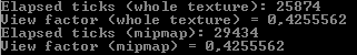
Here is a code snippet for both functions (tex has dimensions of 512x512 pixels).
    float GetPixelMean(Texture2D tex)
    {
        SW.Start();
        int N = tex.Width * tex.Height;
        float[] PixelValue = new float[N];
        tex.GetData(PixelValue);

        float Sum = 0;
        for (int i = 0; i < PixelValue.Length; i++)
        {
            Sum += PixelValue[i];
        }

        long Time = SW.ElapsedTicks;
        SW.Stop();
        Console.WriteLine("Elapsed ticks: " + Time);

        return Sum / N;
    }

    float GetPixelMeanMipMap(Texture2D tex)
    {
        SW.Start();
        float[] PixelValue = new float[1];
        tex.GetData(tex.LevelCount - 1, null, PixelValue, 0, 1);

        long Time = SW.ElapsedTicks;
        SW.Stop();
        Console.WriteLine("Elapsed ticks: " + Time);

        return PixelValue[0];
    }
Maybe the GetData<>() call is the bottleneck?
Calling GetData forces the CPU and GPU to synchronize, which can be very costly. See here for more info:
https://msdn.microsoft.com/en-us/library/windows/desktop/bb205132(v=vs.85).aspx#Accessing
Yeah, it does help quite a lot once I scale up the texture size.
Hello @AcidFaucent,
Just for the sake of completeness, I compared the numerical results from the hemicube approach with analytical results in two simple cases:
- Parallel plates or same dimensions.
- Parallel discs with radius r and 5r.
The maximum error (green) is somewhere around 30 % and is smallest for view factors between 0.2 and 0.5.


It would be interesting to check out how the dual-paraboloid solution compares.
@mgulde sounds about right. Aside from a sampled solution always being off from an analytic one - a hemicube has higher density at the edges that’s going to skew things a great deal (more samples in a band of solid-angles around 45deg outward). Up close you end up with lots of samples in that band and at a distance your samples start to all pile together around the less dense center of the viewing direction.
Just to be sure, you’re only taking the appropriate half of each of the side faces of the cube right?
Yes, I validated it with a couple of sample geometries to get it right.