I am currently working on a project to compute radiative energy transfer across complex geometries. In order to do so between any two objects, one needs to compute the view factor between those objects or - in other words - the amount of surface of one object as seen from the other object.
Traditionally, a lot of this is performed via ray tracing methods. For performance reasons, I would like to use the OcclusionQuery function offered by Monogame / XNA. This function returns the number of pixels which passed the z test after a draw call. To compute the surface area of Object2 visible to Object1, for example, I would perform the following steps:
Place the camera at Object1, facing Object2
Draw the complete scene (every single object in the scene has a specific color)
Perform an OcclusionQuery and redraw Object2
The number of pixels returned from the OcclusionQuery can now be computed into the visible surface area (in orthographic projection)
This works pretty well as long as the objects in question are far apart and only span a small angle. For point-source type illumination, e.g., by the sun, this approach hence works fine.
Now, I would like to compute the radiative energy transfer between objects a lot closer to each other, e.g., between individual components inside a satellite. So, again, I would like to find the view factors / visible surface areas of all the surrounding objects. Since in this case, those objects can span a larger viewing angle, things are getting a bit trickier.
One possible way would be to look into many different directions from each radiating point. If assuming a field of view of pi/2, that would mean 8 different perspectives.
It would be way easier, however, to simply use two FoVs which span pi or a single one spanning 2pi (or 4 pi sr, if you like). As soon as I get close to a FoV of pi, Monogame is seemingly getting in trouble and stops drawing things at all. I assume this has to do with the planar image plane of Monogame and is hence a limitation of the algorithm?
Would you have any ideas on how to solve this problem? E.g., rendering to a spherical image plane or sth.?
You normally do this with a texture cube / renderTargetCube, im basically working on trying to figure out how to get one working as my current project.
It’s a interesting idea to render a full 360 scene.
However.
You can’t map pi2 radians to a image with a regular projection matrix.
Building a matrix to do this may not be possible.
Even if you did or did so with a regular function you would end up with a lot of wasted skewed texel data.
Spheres mapped directly to a square texture (proper) need to be mapped were the backwards point directly behind the camera essentially maps the outer 4 corners of the image. (yes the back point exists on 4 edge points of the image rectangle), thats if you want to be able to wrap across edges so that coordinates are continuous (no other mapping gives continuous coordinates) and mapping then must be transformed to 45 degrees of z rotation. It will still need to be skewed and texels would be lost. As the entire outer edge of the 2d image represents two distinct pi/4 length cross cuts behind the camera on the sphere.
So ya you probably want to go with a renderTargetCube.
Thanks for your thoughts on this issue. I will try to play around using the RenderTargetCube class and see if I can generate some useful output.
I just had a look at my model and might be able to think of another way. Instead of fixing the field of view beforehand as done in most games (I believe), one could build a bounding box around the target object and try to create a camera field of view which exactly fits this bounding box. If the results would be that the FoV would span more than pi, then I would need to come up with an extra solution.
Generally, the RenderTargetCube seems to work, but I have the problem that I do not know how to properly stitch the coordinates of each individual image using orthographic projection.
In case of perspective projection, I can simply choose a 90 deg field of view and render images looking in six directions. In this case, the borders should exactly match and hence the coordinates. But perspective projections have the problem that it is difficult to determine the real size of the object from the number of visible pixels alone.
If changing to orthographic projection, the problem is exactly opposite: Pixel number corresponds to real surface area, but how to make a cube without gaps or overlaps?
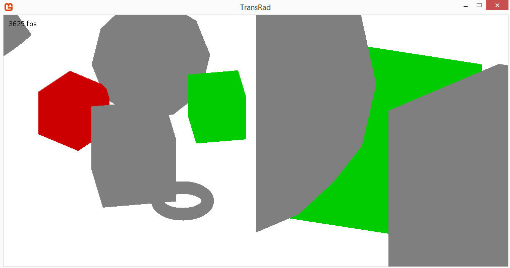
So I instead just render each object as seen from each other object in orthographic projection. This has the disadvantage that I will need to render the scene O(n^2) times (with n being the number of objects) instead of O(n) times, but up until a few hundred objects it should work.
To demonstrate what I am doing: Red is the source object for the thermal radiation, green is the target object. In the left viewport, I see the relative arrangement together with some other objects. In the right viewport, I display the target object as seen from the source object.
But perspective projections have the problem that it is difficult to determine the real size of the object from the number of visible pixels alone.
Explain what you mean?
That is the real size of it - multiply by your transfer map for the lobe and then integrate.
If you intend to find some form of radiation through rendering then you’re going to be using a hemicube and a precomputed table for your transfer function (Lambert for radiation/thermal, pivoted around Euler’s for electrical). Render your hemicube, integrate your values multiplied by the transfer map. Repeat until you’ve covered your absorbed surface to whatever resolution.
There is no analytic form-factor for an obscured object like you’ll have in most any render, you have to integrate. Even if you want to query for an infinitely small point you’re still going to be doing integration over several cosine lobes, no different than calculating PMREMs - which are radiation.
If you render with a perspective camera, the objects will shrink exactly to 50% in length, if the object is twice as far away. So you should be able to calculate the real size if you include distance in your rendering.
But isn’t the heat transfer dependent on the visible surface area anyways, rather than the real object size. If an object is twice as far away from me, I should receive 1/4 the radiation, just like the visible surface area will be 1/4.
Hi @markus,
I believe that’s only true if you look at spherical symmetric surfaces. Also, it depends a bit on the radiation characteristics (e.g., Lambertian). But you are of course right about the 1/z rule. I’ll have to think about it a bit.
What I meant was to include distance for every rendered pixel, not a constant distance value. That should allow you to calculate the real world size for every pixel in your map individually. If you also need the surface normal, you can include that in your rendering as well.
To me it still seems like you wouldn’t need the real world size of the pixels, but maybe I’m missing something, I’m really not a heat-transfer expert.
You were right about the 1/r^2 dependency. The source of my confusion was that I have done something very similar for the sun already, which is basically a point source at infinity. Hence, in this case, I can ignore the distance, the incoming ray density is constant and all rays parallel.
In the case of a radiating surface I will indeed need the surface normal and the depth information for each pixel to compute the radiative heat transfer between individual elements. I am going to check our the hemicube algorithm proposed by @AcidFaucent for that.
Hemicube and fisheye are both for integration on a surface. It sounds more like you’re after an approximate where your object is just an arbitrary point/cube (I assume by element you mean a whole object and not a sample point on an object), in which case you probably want to be using a GBuffer cubemap and sampling that.
Although it’s about light, thermal radiation is mostly the same (it just reacts with participating media [air] and in a multipass for convergence it has a loss - which you may not care about). Most exposure related things can be found in the same fashion just working with different values (kelvin instead of lumen, etc) and different tweaks (static absorption is strongest at perpendicular angles that along the vector to ground and never zero, etc).
The old Hugo Elias article is one of the best sources:
If you get lost, ask and I can toss a bunch of C++ code I use for doing this stuff (determining hemicube coordinates, multiplier map construction, and summation).
Wide but still less than 180 degree views tend to work fine though, something like an 18% inaccuracy compared to a hemicube sampling IIRC which is usually okay for anything non-life/ops-critical.
Hi @AcidFaucent,
You are right, an approximate solution is what I am after. In this particular case, radiative heat transfer between individual components inside the satellite is not a dominant effect. Furthermore, there is no participating medium, since the inside of the satellite is going to be in vacuum.
Thanks for the sources, I will check them out and start working on a solution afterward. If it turns out that it’s too complex for what I have in mind and I have trouble integrating it, I would like to come back to your offer of some C++ snippets.
May I ask where you got the 18 % inaccuracy from? Under what circumstances has this been the case?
May I ask where you got the 18% inaccuracy from? Under what circumstances has this been the case?
From comparing running both a 150deg fisheye and a hemicube (128x128 face resolution) IIRC and the scenario was for light in lux, which is sensible most of the outer degrees are low contribution, and the two have different densities (hemicube is densest per-solid angle at increments of 45deg off-center [cube corners]), as well as the warping of geometry that isn’t highly tessellated when using a high-FOV.
Have you considered the technique involving two parabolic surfaces? I’m not sure what it’s name is - I don’t think it’s the hemi cubes you mentioned - but I’ve used it to circumvent the need for cube maps for omnidirectional point light shadow casting, so it might be relevant to your intent.
The lefthand side shows the scene with the red dots displaying the five camera pointing directions with the camera sitting in the center point. The righthand side is the resulting hemicube texture of the resulting images with the transfer map applied.
The only thing I am lacking now is a fast way to sum over the (float) values of the right image. GetData<Color>() would do the job but is incredibly slow (frame rate drop by a factor of 10 - 100 depending on the resolution of the texture).
Maybe I could use a custom sprite effect to sum over the pixels and then render the result into a new texture. Any ideas are welcome.
If you create a render target with the mipmap flag enabled, it should automatically downsample to a single pixel on the smallest mipmap level. The pixel’s value will be the average of the entire texture. Multiplying this one pixel by the total pixel count should get you the sum.
I never tried that with cube textures, it should work the same though. You just have to do it for all 6 cube faces.