There are some other settings that might be the cause as well.
ill just post this for brevity its just copy pasted so you get the idea.
These can all be set to the graphics device states.
humm thats weird well lighting wont work right on primitives without normals so there’s no point in using it. Though with opaque and cullmode none they should at least all be black and visible.
were did you set your texture. basicEffect.texture = ?
try commenting all that out except
basicEffect.TextureEnabled = true;
basicEffect.AmbientLightColor = new Vector3(.5f,.5f,.5f);
Global.graphics.GraphicsDevice.DrawUserIndexedPrimitives(
PrimitiveType.TriangleList,
tri.Verts,
0, tri.Verts.Length, // try setting that to 2 or 1 see what happens its usually never length
tri.Indexes,
0,
tri.Verts.Length / 3
);
If all else fails make a test project and load those trees all alone draw out one triangle at a time as you test to see exactly what is going on.
Don’t use clone. I got the same problem and just using the effect did the trick: basicEffect = (BasicEffect)MEngineMain.defaultDrawEffect; //.Clone();
As stated in the doc, it only copies mutable data / “vital” data, so it draws black. May it be a bug in the Clone() method ?
Or if clone is used, you have to set manually the texture to use.
I removed the .Clone() part and my objects are using their texture the right way.
Wait wait wait. “Won’t work right without normals”. Is that’s what’s causing it? Because I’m using VertexPositionColor (no normal).
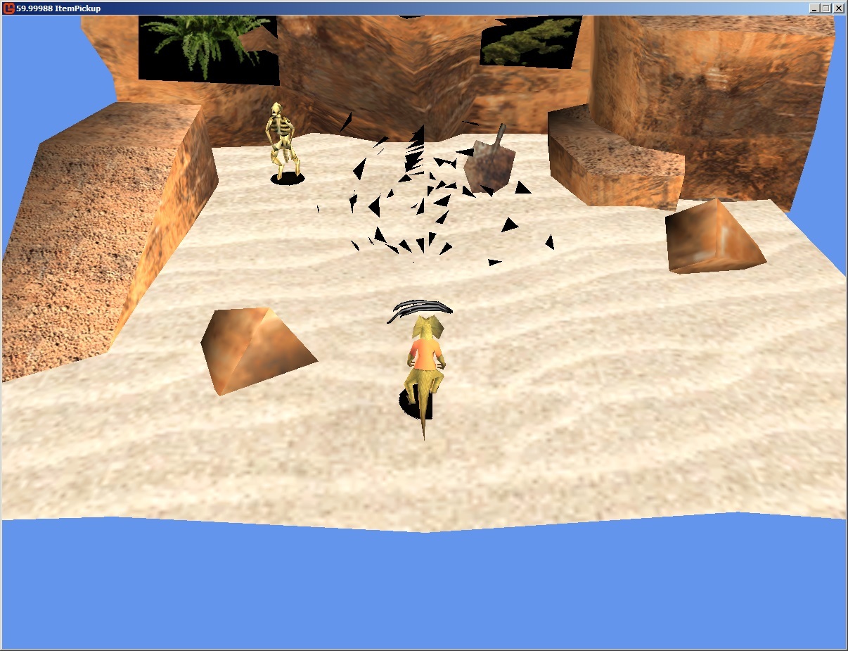
“Though with opaque and cullmode none they should at least all be black and visible.”. They are. I think that’s my fault, I should have mentioned that I wanted some of them to be missing (I’ve programmed it that way). All the triangles I want are being shown, just black instead of with a colour.
Anyways, I tried the following:
// Set the effect.
basicEffect = new BasicEffect(Global.graphics.GraphicsDevice); //(BasicEffect)(MEngineMain.defaultDrawEffect.Clone());
basicEffect.Projection = MEngineMain.Camera.Projection;
basicEffect.TextureEnabled = true;
basicEffect.AmbientLightColor = new Vector3(.5f, .5f, .5f);
@Alkher, you mention “using their texture the right way”. These tri’s don’t have a texture, and because they’re VertexPositionColor, I didn’t think there was a way to give them one. Could that have something to do with it?
Again, when I used VertexPositionNormalTexture with the same script, they didn’t appear black, and appeared with the right texture and everything. I just didn’t want to use textures for what I was doing, and just use colours, which is when the problems started.
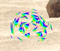
For comparison, here’s how it looks when I use “VertexPositionColorTexture”:
Note that it doesn’t seem to be picking up the Color of the name. The texture I applied is just a generic rainbow texture that I use for debugging purposes. The point though is that it works.
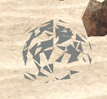
Edit: Here’s what it looks like if I use “VertexPositionColor”, and have basicEffect.Texture = to the rainbow texture above:
humm i think your misunderstanding some basics
textures are the images with the leaves and stuff so how could you draw anything but solid polygons at best with the vertice shaded you cant have lighting without normals generated for each vertice to alter the brightness of the colors.
Without a texture your tree would look like triangles.
Vertex
is the structure.
Position
The position of each point of a triangle.
You need 3 per triangle and 2 triangle make for a square |/|
these vertices have xyz coordinates in your world.
Normal
Normals as opposed to directions have a length or distance total of 1.
They can be thought of as a line sticking out of the surface of a triangle from each vertice they don’t all have to point exactly striaght out from the surface and typically don’t but pretty close ussually to straight out.
These have a distance of exactly one (called normalizing) this is used for lighting by a really cheap math function the dot product. when you dot ( new vector 1,1,1) against , new vector( 1 1 1) ) you get a 1 maximum light intensity. You dot the normals against each other the light is a normal too.
you pass in the direction of a light that is normalized.
Then the gpu draws plots from vertice sides and then between lines on two sides of your triangle it basically lerps all the colors of the vertices and the normals.
It passes those positions to the pixel shader. As it draws each pixel in the pixel shader it takes the lerped normal from between vertices and dots it against the light normal direction you gave it as a lightDirection for lightDirection0 1 2 ect.
Without the normals on the vertices lighting is just faked eg the result is constant. What you see is just a color or ambient which is just like saying the result of this dot product is always one * some value.
When you set a color as ambient it cant change between vertices its a constant intensity.
Color:
Each vertice can have a color and a set of texture coordinates.
As previously just like the normal and positions are lerped between vertices sides then lines are plotted between to fill the triangles as these positions are lerped the color can be lerped between points as well.
However this is just color between vertices if a triangle has 3 vertices each with a different color of R G or B purely then as a line is draw between say vertice A fully red to vertice B fully blue. in the center of the line that point will have about 128 red and blue in the center of the triangle itself it will have about 128 red green and blue.
Texture
A image is a textue a image has a Width and a Height when we say U,V we are talking about vertex positions that relate to width and height were 1 u 1 v = Width and Height of the image.
0 u 0 v is the start of the texture when you assign a uv to a vertice your assigning u * image.Width = x image pixel position like wise for y and height.
Again the triangle lerps between the positions on the triangle vertice uv’s and figures out were its grabing the a colored texel for your image when it draws.
All that said without a texture or a normal you can see it hasn’t got much to work with.
if you want all of them add the below i don’t think its included by default in monogame i don’t know why and i don’t know if basic effect will work right with it though i imagine it should.
    public struct VertexPositionNormalColorTexture : IVertexType
    {
        public Vector3 Position;
        public Vector3 Normal;
        public Color Color;
        public Vector2 TextureCoordinate;

        public static int SizeInBytes = (3 + 3 + 1 + 2) * sizeof(float);
        public static VertexDeclaration VertexDeclaration = new VertexDeclaration
        (
              new VertexElement(VertexElementByteOffset.PositionStartOffset(), VertexElementFormat.Vector3, VertexElementUsage.Position, 0),
              new VertexElement(VertexElementByteOffset.OffsetVector3(), VertexElementFormat.Vector3, VertexElementUsage.Normal, 0),
              new VertexElement(VertexElementByteOffset.OffsetColor(), VertexElementFormat.Color, VertexElementUsage.Color, 0),
              new VertexElement(VertexElementByteOffset.OffsetVector2(), VertexElementFormat.Vector2, VertexElementUsage.TextureCoordinate, 0)
        );
        VertexDeclaration IVertexType.VertexDeclaration { get { return VertexDeclaration; } }
    }
public struct VertexElementByteOffset
{
    public static int currentByteSize = 0;
    public static int PositionStartOffset() { currentByteSize = 0; var s = sizeof(float) * 3; currentByteSize += s; return currentByteSize - s; }
    public static int Offset(float n) { var s = sizeof(float); currentByteSize += s; return currentByteSize - s; }
    public static int Offset(Vector2 n) { var s = sizeof(float) * 2; currentByteSize += s; return currentByteSize - s; }
    public static int Offset(Color n) { var s = sizeof(int); currentByteSize += s; return currentByteSize - s; }
    public static int Offset(Vector3 n) { var s = sizeof(float) * 3; currentByteSize += s; return currentByteSize - s; }
    public static int Offset(Vector4 n) { var s = sizeof(float) * 4; currentByteSize += s; return currentByteSize - s; }

    public static int OffsetFloat() { var s = sizeof(float); currentByteSize += s; return currentByteSize - s; }
    public static int OffsetColor() { var s = sizeof(int); currentByteSize += s; return currentByteSize - s; }
    public static int OffsetVector2() { var s = sizeof(float) * 2; currentByteSize += s; return currentByteSize - s; }
    public static int OffsetVector3() { var s = sizeof(float) * 3; currentByteSize += s; return currentByteSize - s; }
    public static int OffsetVector4() { var s = sizeof(float) * 4; currentByteSize += s; return currentByteSize - s; }
}
With custom vertex data you have to calculate them the normals yourself with a function.
You do that with a cross product on each triangles vertice sides.
For a triangle with vertices A B C
d0 = B - A;
d1 = C - B;
d0.Normalize();
d1.Normalize();
n = cross( d0 , d1);
You can apply that to each vertice for a dirty version.
if you cross n = cross( d1 , d0);
This changes the culling or the direction of the normal it inverts it.
Thats what cull clockwise and counterclockwise is about the gpu use that to not draw entire triangle vertices or pixels to speed things up.
When you don’t use indices or normals the gpu does the calculation itself using a dirty version.
If you are culling them depending on the order you passed in the vertices, if not culling it ignores the sign.
Here is mine its basically how you do it i really should normalize n0 n1 i dunno why i didn’t.
This is done only once when you create them typically you would save the results to file and load it.
        /// <summary>
        /// This method creates smooth normals from a quad structured vertice mesh array
        /// </summary>
        private PositionNormalColorUv[] CreateSmoothNormals(PositionNormalColorUv[] vertices, int[] indexs)
        {
            // Under quads there are two triangles per quad
            // such that the triangle associated with normals in a proper indexed vertice list
            // will describe per triangle all shared normals for each vertice.
            // hence each vertice will be shared by 6 triangles ranging from 0 to 5
            // so that for each vertice we must must calculate the surrounding normals to average them.

            int tvertmultiplier = 3;
            int triangles = (int)(indexs.Length / tvertmultiplier);

            // Loop the vertices
            for (int currentTestedVerticeIndex = 0; currentTestedVerticeIndex < vertices.Length; currentTestedVerticeIndex++)
            {
                // Reset are sum and total counts
                float total = 0;
                Vector3 sum = Vector3.Zero;

                // loop thru each triangle
                for (int t = 0; t < triangles; t++)
                {
                    int tvstart = t * tvertmultiplier;
                    int tindex0 = tvstart + 0;
                    int tindex1 = tvstart + 1;
                    int tindex2 = tvstart + 2;
                    var vindex0 = indices[tindex0];
                    var vindex1 = indices[tindex1];
                    var vindex2 = indices[tindex2];
                    // Test each triangle for the currentTestedVertice presence
                    if (vindex0 == currentTestedVerticeIndex || vindex1 == currentTestedVerticeIndex || vindex2 == currentTestedVerticeIndex)
                    {
                        // Obtain a orthagonal direction from the surface of this triangle.
                        // This is basically a non unit length normal.
                        // Multiply by some amount 10 here to increase precision and avoid nans.
                        var n0 = (vertices[vindex1].Position - vertices[vindex0].Position) * 10f;
                        var n1 = (vertices[vindex2].Position - vertices[vindex1].Position) * 10f;
                        // Sum the cross product and increment the total
                        var cnorm = Vector3.Cross(n0, n1);
                        sum += cnorm;
                        total += 1;
                    }
                }
                // Find the average
                if (total > 0)
                {
                    var averagednormal = sum / total;
                    // Normalize the result
                    averagednormal.Normalize();
                    // Assign the normal to the vertice
                    vertices[currentTestedVerticeIndex].Normal = averagednormal;
                    if (showSmoothing)
                    {
                        Console.WriteLine(" SmoothedNormals: vertices[" + currentTestedVerticeIndex + "].Position:  " + vertices[currentTestedVerticeIndex].Position);
                        Console.WriteLine(" SmoothedNormals: vertices[" + currentTestedVerticeIndex + "].Normal:  " + averagednormal);
                    }
                }
            }
            return vertices;
        }
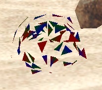
This is with color and textures turned off the color is ambient white passed in.
basically.
The normals when it matches the light direction as shown brighten those vertices that match via the result of the dot product that ranges from
-1 to 0 black. |_
to .7 at a 45 degree light to normal difference |/.
Then to 1 , when they align | |
This is why the normals stick out orthagonally from the surface.
When the result of the dot is 1 we multiply color.White by it and get the full white color 255 * 1.
When the dot is say 0 and you multiply 255 r g b by 0 you get 0 so
Shown below the flat area all has normals that stick out like the green arrow from the surface.
the light is the rotating green arrow basic effect sets it as direction so you can imagine that rotating green arrow pointing in the reverse direction and the dot result between them.
That’s this shader i posted here, with those vertice normals generated by the above function.
The relevant part is here below basic effect does something similar.
Intensity.
saturate just turns negatives results into 0;
the col is just my function it can be whatever
i rip out part of the regular lighting to directly replace it with some ambient color.
I took your advice and made a custom Vertex class which included Position, Color, AND Normal:
public struct VertexPositionColorNormal : IVertexType
        {
            public Vector3 Position;
            public Color Color;
            public Vector3 Normal;

            public readonly static VertexDeclaration VertexDeclaration = new VertexDeclaration(
            new VertexElement(0, VertexElementFormat.Vector3, VertexElementUsage.Position, 0),
            new VertexElement(sizeof(float) * 3, VertexElementFormat.Color, VertexElementUsage.Color, 0),
            new VertexElement(sizeof(float) * 3 + 4, VertexElementFormat.Vector3, VertexElementUsage.Normal, 0)
            );

            public VertexPositionColorNormal(Vector3 pos, Color color, Vector3 normal)
            {
                Position = pos;
                Color = color;
                Normal = normal;
            }

            VertexDeclaration IVertexType.VertexDeclaration
            {
                get { return VertexDeclaration; }
            }
        }
Note that this is an exact copy of the one found in this tutorial: Reimers Tutorial
Using that (and manually calculating the normal) still didn’t work, but then I did this:
Oh, and if anyone comes here and this still didn’t solve the issue: I had accidentally put in the line:
basicEffect.TextureEnabled = true;
at one point, but didn’t set the effect’s texture. This was another cause of the black effect.
Thanks for helping me out @willmotil and @Alkher! I think I might make a couple more custom vertex declarations, now that I know how it’s done! Out of curiosity, would converting an entire model to a custom vert format be wise (in terms of processing)? The effect you see in my snapshots takes a basic sphere.fbx model that I imported, converts it to vertices, and then splits them apart. If I wanted to say, do that in large quantities, would it be smart to use this method?