A CRT effect such as those shown here and low poly models rendered to a low-resolution render target should get what you want. The dinosaur skeleton in @Milun’s post above looks like a PS1-era screenshot.
1 Like
ROFL. @Milun will be happy 
1 Like
I suppose not the scanlines as I avoid those in games that feature it, but I guess the method by not using linear filtering or any filtering is the only way to get the effect…
But still a pixeling effect such as those types in games where they obscure private parts for example might be handy for similar reasons or just to create a pixilation effect… I will likely never use 2D for games, just not in my DNA  [I mean create a strictly 2D only game]
EDIT
Relating to the outline effect, this video shows it being used a lot…
Oh this?

Will, how did you avoid linear filtering on the model?
OMG that is exactly what I am looking for with the square polygons too… well, almost…
Actually… I think my level design will be sharp visuals kind of like vector graphics and just the character models will have the effect err lack of effects applied to give that classic look to them… but the levels will have high fidelity visuals in contrast…
Just uploaded that video I mentioned earlier, it might take a few more minutes to show up here, still uploading. at the time of posting here
Not sure but I think the sky uses scanlines?
So as you can see, that disorganised square polygons is what I am aiming for… whether organised or not [I understand the disorganised projection is due to the way it was processed on each change in the scene and every frame forces the polygons to show up as if they have rotated somewhat, a very subtle effect though] I think it can steal some processing time away from the render time and increase frame rates…
Some good examples here
Trying to find the video that explains why PSOne SegaSaturn consoles used square polygons for performance reasons… but will post it if I find it again…
QUADS! that was the word… yeah quads based 3D rendering instead of triangles…
Can I throw a request in for a CRT shader?
(You’ll have to excuse me, I don’t know drawing terminology very well off the top of my head).
I used PointClamp/PointWrap (comes default with MonoGame). I also didn’t use aliasing for the models, which is why they have those sharp, jagged edges. Low resolution textures also help it out. I also deliberately lowered the amount of colours on each of my textures in Photoshop so that they only have 16/32 colours depending on the size. OH! Also, I rendered my entire scene to a texture that’s half the size of the screen, then stretched it to fit, which enlarged the pixels (basically, I deliberately lowered the resolution).
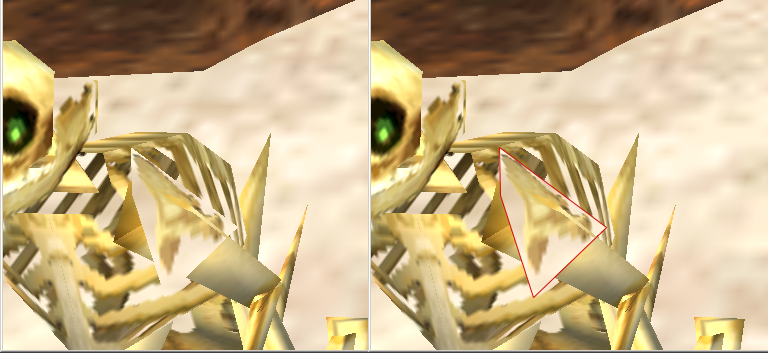
I actually too would like a PSX shader, but for a different reason. On PSX, whenever the camera moves, vertices/textures seem to “wobble” almost. I don’t know if anyone else has noticed it, but it’s definitely there. As you can see, I’ve managed to simulate a PSX style almost entirely, but I’m missing that last part. Thought it’s not as important as fixing that transparency glitch I’m having.
Nope. Will report results when I get home. Thanks!
Thank you very much ![]()
just for clarity…
It really should be though of as point and clamp or point and wrap independently.
The two things are really separate.
While both denote how texels are or will be sampled from a image they are different aspects.
point anstropic and linear denote how the card grabs the texels from the source image and outputs them but mostly its about how it grabs texels and if it will blend them via some way, while interpolating between two vertices line rasterization’s.
While nowdays its a little more complex its still the same basic principle.
Ill illustrate with a pseudo example:
if you have a line going from A to B that must be plotted to screen.
Lets say its total width is 10 pixels.
The uv total texel width is say 20 texels.
Point linear and ansostropic denote how the pixels are grabed.
To say if im a line rasterizing gpu on position x 5 of this line im plotting were do i get the pixel.
When the source texels are twice as large as the destination and what about the reverse?
Well
lets say that the texel grab width is found by texels / pixels 20/10 = 2
lets say that the pixel plot width is found by pixels / texels 10/20 = .5
the plot position is x = .5 * 10 = 5
so the plot start is 5 the end is 5+ .5 = 5.5
the grab start is .5 *20 =10
and the end is 10 +2 -1 = 11
so i get texel 10 and 11 to be drawn to 5.
Were this matters is really dependent on the size of the sampling.
With point we get the texel at 10 that’s the point we grab we don’t worry about anything else unless antialiasing is on and it can worry about the rest separately…
With linear we get 10 and 11 to blend to 5.
With ansiostropic we might get 9 10 11 12 to blend to 4 5 6
In the opposite case 10/20 = .5.
linear might evaluate to the equivalent of point.
With ansostropic we might sample surrounding texels in either down or up sampling.
With clamp and wrap we are simply defining how u,v 's from 0 to 1 are handled when they extend past 0 or 1.
e.g.
clamp
if(x < 0) x = 0;
if(x > 1) x =1;
wrapped
if(x < 0) x = x +1;
if(x > 1) x = x -1;
though this is probably modulous’ed
While none of this is spot on really its not even close its just basically to convey the ideas
This is how it used to be done and its a lot more fancy but the general principle still lies beneath it.
You should think of the first part as How we will Interpolate the second word as How we handle grabbing texels past texture edges Linear / Clamp,
It just occured to me these are such old words now that many people probably have no idea what they really relate to ‘line rasterization’.
1 Like
Yeah, sorry about that. Like I said, I’m not good with this terminology.
I thought the only difference between Clamp/Wrap for Point was that one would repeat the edge pixels when the UV went outside the map, and the other would repeat them. It’s really up to you how you structure your models really. I personally use PointWrap, since saving on space by repeating a texture is a very common practice done by PSX/N64 games. Sorry, I don’t know that much about this stuff outside of that. I accomplish most of my effects with how I create the models and textures. I’ll post an example when I get home if you want.
1 Like
point is point its the cheapest and most basic i think of it as crisp. linear in most cases will act the same or nearly the same when the texels to be drawn are about the same size as the texels to be ploted as pixels.
When your down sampling (or is that up i forget) drawing a larger texture to a smaller area point is more efficient but linear will look better. Up sampling makes little difference typically. Ansostropic basically does anti-aliasing type sampling either way.
Clamp and wrap don’t depend on the interpolation they only deal with how edges are handled by it.
They are separate beasts but have cumulative effects.
I wrote a polygon line rasterizer though a long long time ago so i basically had to deal with all that on the algorithm level.
All that said i still suck with shader syntax.
In fact im struggling with alpha blending and depth on my shader right now like the wording to get the algorithm data to function in it, not the algorithm itself lol.
2 Likes
Still very fresh to me…
I will play with Blender soon and see if I can get something going…
Alternatively I have been thinking of Polygon Colouring… though not sure if it is a good idea… as shaders require a texture right?
No you should be able to make a custom vertex and effect without without a texture.
I didn’t test it but it should work…
There is a feature request for this as a new spritebatch overload.
I have full class that does this with multitextures but its a mess right now id rather not post it.
    public struct VertexPositionColor : IVertexType
    {
        public Vector3 Position; // 12 bytes
        public Color Color; // 4 bytes

        public static VertexDeclaration VertexDeclaration = new VertexDeclaration
        (
          new VertexElement(VertexElementByteOffset.PositionStartOffset(), VertexElementFormat.Vector3, VertexElementUsage.Position, 0),
          new VertexElement(VertexElementByteOffset.OffsetColor(), VertexElementFormat.Color, VertexElementUsage.Color, 0)
        );
        VertexDeclaration IVertexType.VertexDeclaration { get { return VertexDeclaration; } }
    }
    /// <summary>
    /// This is a helper struct so i don't have to use my fingers to add bytes :)~
    /// </summary>
    public struct VertexElementByteOffset
    {
        public static int currentByteSize = 0;
        public static int PositionStartOffset() { currentByteSize = 0; var s = sizeof(float) * 3; currentByteSize += s; return currentByteSize - s; }
        public static int Offset(float n) { var s = sizeof(float); currentByteSize += s; return currentByteSize - s; }
        public static int Offset(Vector2 n) { var s = sizeof(float) * 2; currentByteSize += s; return currentByteSize - s; }
        public static int Offset(Color n) { var s = sizeof(int); currentByteSize += s; return currentByteSize - s; }
        public static int Offset(Vector3 n) { var s = sizeof(float) * 3; currentByteSize += s; return currentByteSize - s; }
        public static int Offset(Vector4 n) { var s = sizeof(float) * 4; currentByteSize += s; return currentByteSize - s; }

        public static int OffsetFloat() { var s = sizeof(float); currentByteSize += s; return currentByteSize - s; }
        public static int OffsetColor() { var s = sizeof(int); currentByteSize += s; return currentByteSize - s; }
        public static int OffsetVector2() { var s = sizeof(float) * 2; currentByteSize += s; return currentByteSize - s; }
        public static int OffsetVector3() { var s = sizeof(float) * 3; currentByteSize += s; return currentByteSize - s; }
        public static int OffsetVector4() { var s = sizeof(float) * 4; currentByteSize += s; return currentByteSize - s; }
    }

        // in game1
        Effect TestEffect;
        VertexPositionColor[] vertices;
        int[] indices;

        // in load
        // TestEffect = Content.Load<Effect>("TestEffect");

        private void CreateColorQuad(Color a, Color b, Color c, Color d)
        {
            float z = 0.0f;
            float adjustment = .0f; // direct virtual translation should be a vector2
            float scale = 1f; // scale 2 and matrix identity passed straight thru is litterally orthographic
            vertices = new VertexPositionColor[4];

            vertices[0].Position = new Vector3((adjustment - 0.5f) * scale, (adjustment - 0.5f) * scale, z);
            vertices[0].Color = a;

            vertices[1].Position = new Vector3((adjustment - 0.5f) * scale, (adjustment + 0.5f) * scale, z);
            vertices[1].Color = b;

            vertices[2].Position = new Vector3((adjustment + 0.5f) * scale, (adjustment - 0.5f) * scale, z);
            vertices[2].Color = c;

            vertices[3].Position = new Vector3((adjustment + 0.5f) * scale, (adjustment + 0.5f) * scale, z);
            vertices[3].Color = d;

            int[] indices = new int[6];
            indices[0] = 0;
            indices[1] = 1;
            indices[2] = 2;
            indices[3] = 2;
            indices[4] = 1;
            indices[5] = 3;
        }
        // called by draw after graphicsdevice clears and before spritebatch
        public void DrawTechniqueA()
        {
            GraphicsDevice.RasterizerState = RasterizerState.CullNone;
            var worldviewprojection = Matrix.Identity;
            TestEffect.Parameters["gworldviewprojection"].SetValue(worldviewprojection);
            foreach (EffectPass pass in TestEffect.CurrentTechnique.Passes)
            {
                pass.Apply();
                GraphicsDevice.DrawUserIndexedPrimitives(PrimitiveType.TriangleList, vertices, 0, 4, indices, 0, 2, VertexPositionColor.VertexDeclaration);
            }
        }
…
    // copy paste into a pipeline created effect.fx
    // __________  TestEffect ________________
    #if OPENGL
    #define SV_POSITION POSITION
    #define VS_SHADERMODEL vs_3_0
    #define PS_SHADERMODEL ps_3_0
    #else
    #define VS_SHADERMODEL vs_4_0_level_9_1
    #define PS_SHADERMODEL ps_4_0_level_9_1
    #endif

    float4x4 gworldviewprojection;

    //Texture2D Texture;
    //sampler2D TextureSampler = sampler_state
    //{
    //    Texture = <Texture>;
    //};

    struct VertexShaderInput
    {
        float4 Position : POSITION0;
        float4 Color : COLOR0;
        //float2 TexureCoordinate : TEXCOORD0;
    };

    struct VertexShaderOutput
    {
        float4 Position : SV_Position;
        float4 Color : COLOR0;
        //float2 TexureCoordinate : TEXCOORD0;
    };

    struct PixelShaderOutput
    {
        float4 Color : COLOR0;
    };

    VertexShaderOutput VertexShaderFunction(VertexShaderInput input)
    {
        VertexShaderOutput output;
        output.Position = mul(input.Position, gworldviewprojection);
        output.Color = input.Color;
        //output.TexureCoordinate = input.TexureCoordinate;
        return output;
    }

    PixelShaderOutput PixelShaderFunction(VertexShaderOutput input)
    {
        PixelShaderOutput output;
        //output.Color = tex2D(TextureSampler, input.TexureCoordinate) * input.Color;
        output.Color = input.Color;
        return output;
    }

    technique TechniqueA
    {
        pass
        {
            VertexShader = compile VS_SHADERMODEL VertexShaderFunction();
            PixelShader = compile PS_SHADERMODEL PixelShaderFunction();
        }
    }
1 Like
Nah, sorry, CullNone didn’t work.
My settings for the GraphicsDevice are as follows:
GraphicsDevice.SetRenderTarget(scene);
GraphicsDevice.Clear(Color.CornflowerBlue);
GraphicsDevice.DepthStencilState = DepthStencilState.Default;
GraphicsDevice.BlendState = BlendState.AlphaBlend;
GraphicsDevice.SamplerStates[0] = SamplerState.PointWrap;
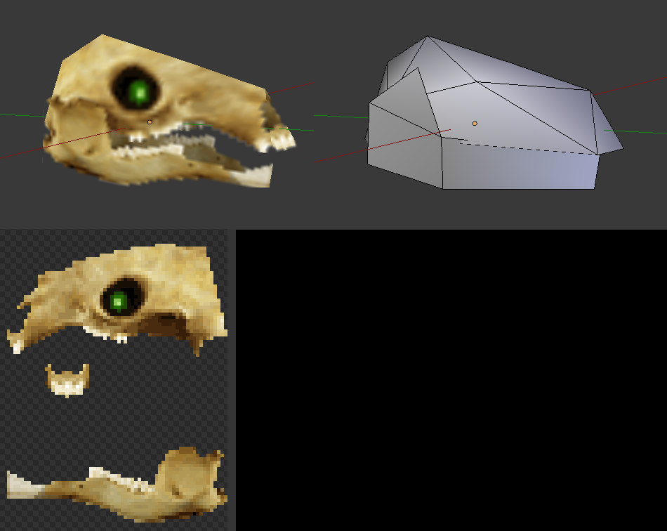
Pretty simple really. Most of the style comes from the model, which looks like this:
1 Like
I find it quite umm… refreshing that I am not the only dev on here that appreciated the golden era of 3D games 

1 Like
I miss Doom/Doom 2 times, with IPX multiplayer etc so many nights spent on coop to kill cyberdemons full of pixels ^^
Maybe I’ll add an option to pixelate the renders in my engine. Just for fun.
1 Like
What does ypour Shader look like
Is it possible to get the currently set color of the current pixel before setting it to say if i clear the backbuffer with blue and i am about to draw a quad how can i grab the color that is already there to compare it with the current quad pixels color ? Or is that not possible i was trying to do it yesterday to no avail.
I want to implement something like this in a shader but im having a hard time seeing thru the hlsl syntax on how to do it. This is actually a cpu image shading function for a paint algorithm i wrote a few years ago.
I have a bunch of them. I want to get them onto the gpu as shaders though i think if i can do it with just one i can get them all in and make a really good one.
        // were d and s denote source and destination
        //case 1:// Blend Higher Alpha of either determines which is retained
        //    S_Alpha = (float)(source.A * .0039215f);
        //    D_Alpha = 1.0f - S_Alpha;
        //    a = 0;
        //    r = (byte)(S_Alpha * (float)source.R + D_Alpha * (float)dest.R);
        //    g = (byte)(S_Alpha * (float)source.G + D_Alpha * (float)dest.G);
        //    b = (byte)(S_Alpha * (float)source.B + D_Alpha * (float)dest.B);
        //    // here the higher alpha is retained but not neccessarily the maximum of 255 even when blending two alpha components
        //    if (source.A >= dest.A) { a = source.A; }
        //    else { a = dest.A; }
        //    if (a > 255) { a = 255; }// safety
        //    dest = new Color(r, g, b, a);
// break;impossible, Use blendstates to make math operations with previous colors.
Or use a rendertarget as input and another rendertarget as output.
How would i approach this with rendertargets ?
I cant use two at once right or can i get the current color from a rendertarget as i draw to it ?
I need the full spectrum rgba depth of the current pixel or what it is before i set the new one.
As well as what im sending in which of course is accessible as i send it.
you can’t read the rt you write to.
You can only write to RT1
Read from RT1, write to RT2
Or use blendstates.
Humm im running on gl and i don’t think blendstates are working properly. Though ill admit i only used them a little bit in xna and im not very good with them.
Still it begs the question how do the blend states do it, if its not possible on the gpu in hlsl ?
Shader… shader… Uh… I don’t think I have one? I’ve dabbled in getting them working in MonoGame, but the best result I got was “black”, so I sorta stopped there.
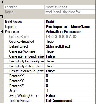
I don’t know if this will help, but all my models are imported with these settings.