Here’s an explanation of how I did it. As I said, this will require two shadow depth maps (the likes of which I presume you used for your other light sources), one for each hemisphere.
Please excuse the crudity of this model; I illustrated it hastily in Paint.
Furthermore, for simplicity, I’m demonstrating this in 2D, but it’s easily transferable to 3D analogously.
The process for creating each hemisphere’s depth map differs from that of other light types primarily in that we have to project the vertices onto the hemisphere in a predictable way such that we can later sample the corresponding points.
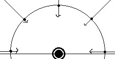
In this illustration, see that the incoming rays (the depth info that we’re trying to record) is going to the point light, but we’re going to imagine writing them onto the surrounding hemisphere.
Problem is, obviously, that we don’t have a hemisphere on which to write; we have square render targets. So we need to transform the incoming position data onto a flat surface.
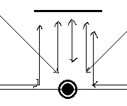
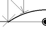
The way that we can project omnidirectional rays into parallel ones, as illustrated, is through the use of a parabolic mirror. Or, at least, that’s how we’re going to imagine it.
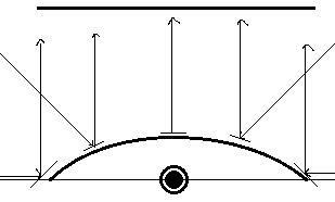
If I can figure out where the incoming rays intersect this parabola, I can place it onto the render target accordingly. For example, that leftmost ray will strike the leftmost point of the parabola (which is angled 45 degrees), and be reflected straight up onto the left edge of the render surface.
But in order to know where the ray intersects the parabola, I need to know its equation. As stated above, the left edge, coordinates (-1, 0), should be angled 45 degrees, or have a slope of 1. The right edge, coordinates (1, 0), should have a slope of -1, and the exact centre (x=0) should have a slope of 0. Therefore, dz/dx = -x.
We could then solve the exact equation of the parabola, but as it turns out, this is all we need. Just recognise, however, that that differential equation above is the slope of the tangent line, whereas the normal - that which is perpendicular to the tangent - is what is going to help us with the reflection. Therefore, we need to consider the “opposite reciprocal”: dx/dz = x.
To compute the normal of reflection, we basically just have to average the unit displacement - the normalised vector between the point light and any vertex that we’re projecting - and the direction to which it’s being reflected.
float3 dd = input.Position - LightPosition;
float3 normal = normalize(normalize(dd) + float3(0, 0, 1)); // or whatever
With this normal vector’s ratio of Δx to Δz and the equation above, we can then identify the x coordinate at which to relocate it, which, again, is simply that aforementioned ratio.
Then, repeat this same logic for the y coordinate.
float distance = length(dd) / MAX_DEPTH;
output.Position = float3(normal.x/normal.z, normal.y/normal.z, distance);
So it turns out, that lengthy explanation aside, it’s actually quite a simple solution. Just gotta do this once for the positive z direction, and again for the negative z direction.
When it comes to sampling the depth from this depth map, just repeat the process: find the direction to the vertex in question, average it with the appropriate z direction, and the resulting Δx/Δz and Δy/Δz ratios will give you the point to sample on the appropriate hemisphere map, depending on the sign of Δz. (Just don’t forget to transform those results into texture coordinates!)
