But that’s what I said, I didnt say to render them just offested, I said use sillhouettes to get shadow drop.
"So, you will be offsetting silhouttes according to direction between given light " and you will do that in shader when accumulating lights. That vector will be calculated per pixel in pixel shader, it will happen in grand total of All lights x Screen resolution, classic deferred rendering (actually there will be some clips based on attenuation.
I don’t quite understand. The light pixel shader lights up each pixel if there isn’t a shadow on that pixel. So in my current solution, it samples a shadow texture in that position to check. But in this one when the light pixel shader samples a sillhoutte pixel and calculates the shadow pixel position it won’t be able to act on it because it’s a different pixel it’s currently applying lighting to.
I think I might write demo, it will be faster. You are accumulating lit up pixels, shadows will appear naturally as unlit pixels.
That would be very much appreciated. Thanks a lot!

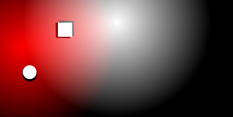
my world to screen recalculation is slightly off somewhere but other than that as proof of concept it should do.
1 Like
Seems about right. Could you send a dropbox link to the project or something, so I can see how it’s done please?
I will PM it, there are several things you need to reliaze:
This is prototype to show how and point here was not to lose much time on it, there are lot of things you don’t want to do in final project, first you WILL want to cache shader parameters, you MIGHT want to batch lights, you DON’T want to recalculate into screen space like this being bothered by aspect ratio of screen, and more things like this. It should be obvious, just making sure there is no communication noise.
Thanks, I’ll keep that in mind of course.
If you need help to remove distortion from “shadows” let me know, all you need to do should be projection along the ray to target plane.

Interesting, well, see how that edge is skewed? I suppose it will also remove this artifact. Just think of that as full 3d case and you calculate distance between planes along the ray casted from source to further plane, this was mainly to show how to handle general render target approach for this case.
This is how you calculate the offset currently, could you write what you had in mind in pseudo code or something, please?
float2 lightVec =  lightPosSS.xy - PSIn.TexCoord.xy;
float2 lightDir = normalize(lightVec);

float2 offset = (lightDir * planeDistance) / viewport;
//we will tap into offseted cords and get simplified shadow term
float shadowTerm= tex2D(Sampler, PSIn.TexCoord + offset).a;Alright, I am not sure I will get to it today, but I might.
Much appreciated
Are you sure? The size of each vertex is going to be quite large at least: position: 12 bytes, light position; 12 bytes, texture coordinates: 8 bytes, light color: 4 bytes, light strength + decay: 8 bytes = 44 bytes per vertex. This is going to be passed from the CPU to the GPU to the vertex shader to the pixel shader. I’m not sure what the performance consequences are.
At this count… absolutely ridiculously none. You are going to pass those parameters to GPU in any case.
Yes, you’re right. But what about vertex shader to pixel shader? The vertex count is going to be very small, but the amount of pixels processed could be tremendous.
You might want to do some research for yourself on that.
I actually tried batching lights on my previous solution a while ago, I remember it as the GPU usage became greater and vertex struct when drawing on the CPU started generating garbage. I don’t recall a significant CPU boost. Besides the point where the amount of draw calls from lights starts to throttle the CPU the GPU has long past been set on fire, unless the lights are very small.
Also on here it is recommended that the amount of data passed to the pixel shader is kept to a minimum, at least that’s how I interpreted it (Pack variables and Interpolants): https://docs.microsoft.com/en-us/windows/desktop/direct3dhlsl/dx-graphics-hlsl-optimize
Done

I have to run for about an hour, then I will show you underlying math / pictures for this. I believe it will be more helpful than just sharing code.
As far as performance goes: you can batch lights also be doing several light passes each drawcall (lets say four by feeding shader with arrays)
Anyway, advice (ignore this if your are working on android game tho): Performance of modern computers is insane, perfect optimization cost ridiculous amount of time. Especially if you are single developer working on 2D title there is no point to invest too much time into optimizing every drawcall, obviously, you have to be aware of doing absolutely stupid stuff but don’t worry about doing everything in most efficient way. Lot of optimizations can be done later, don’t burn yourself over spending too much time over every single detail, when you are not sure just profile your game and then decide if performance cost is worrysome.
Alright:
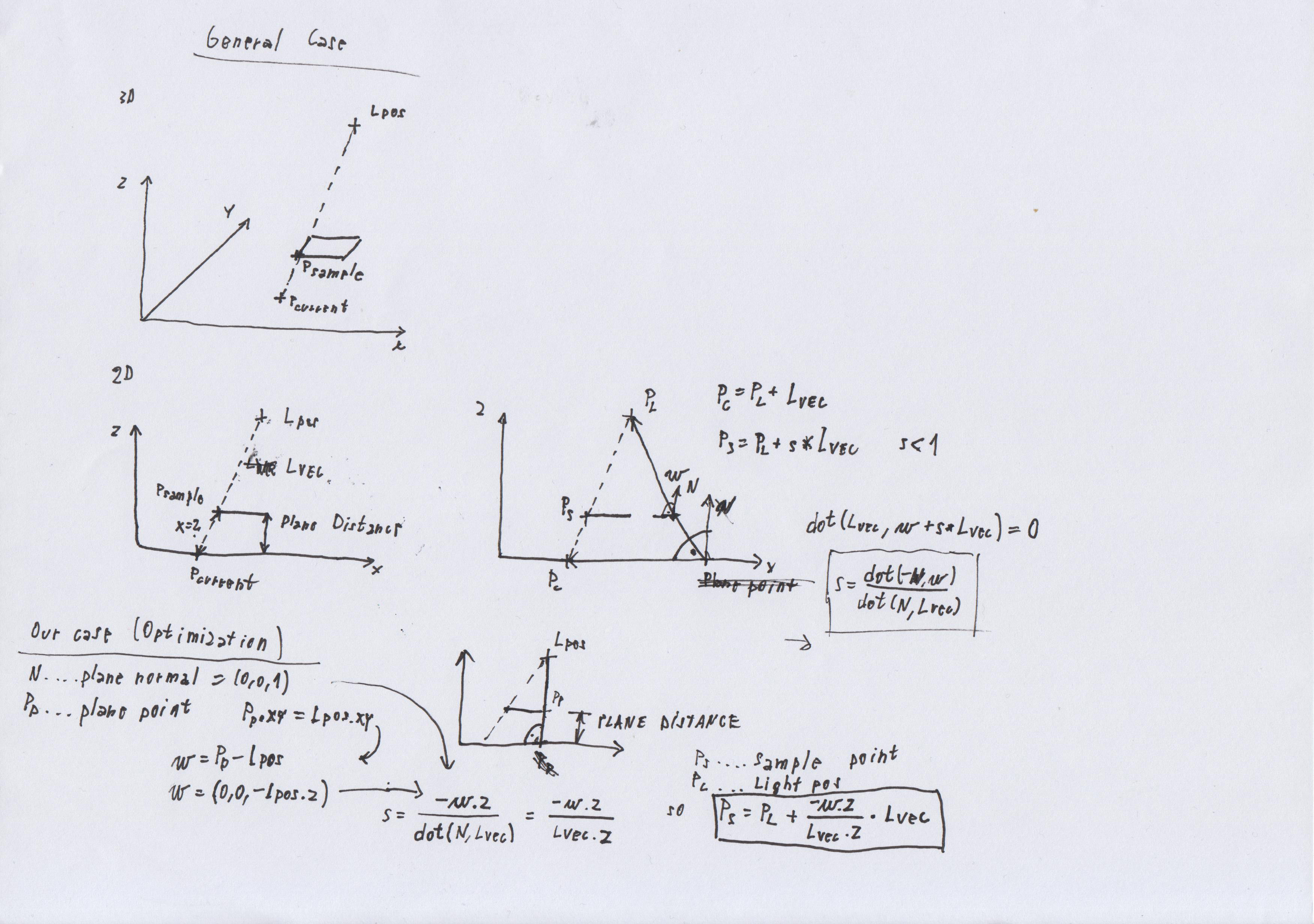
If you can’t read my handwritting for which I absolutely wont blame you, I did a bit of googling and found:
http://geomalgorithms.com/a05-_intersect-1.html
Which will get you to same result while being readable…
Optimization for our case comes from fact that normal of our plane is (0,0,1) so dot product is simply z coordinate of given vector and that we can chose our point from plane to be directly under light (so vector from that point to light is (0,0,Lpos.z))
And important thing: It is better to do this in world space and then get screen space coords for sampling point, also attenuation will become much less clunky, so it will be just
saturate(1.0f - length(lightVec) / attuneation)