This more of a technical difficulty i have with using monogame, with my code specifically. I tried asking it to stack exchange website (link) and i got no reply, even though i think it should not be that hard. I am sure someone must have done something similar when wanting to draw a 3D model in his 2D game. To give you a background, the model is a brick in an arkanoid game.
Here is the question:
I am trying to transform a 2D point, (in the following example (100,100)) into 3D world coordinates, in order to draw my 3D Model named TestModel in XNA/Monogame. Here is my attempt:
Matrix[] transforms = new Matrix[TestModel.Bones.Count];
TestModel.CopyAbsoluteBoneTransformsTo(transforms);
ModelMesh mesh = TestModel.Meshes[0];
BasicEffect effect = (BasicEffect)mesh.Effects[0];
float Scale = 1.2f;

effect.View = Matrix.CreateLookAt(new Vector3(0.0f, 0.0f, 6115.0f),
     Vector3.Zero, Vector3.Up);
effect.Projection = Matrix.CreatePerspectiveFieldOfView(MathHelper.ToRadians(45.0f),
    1.6666f, 1.0f, 10000.0f);
effect.EnableDefaultLighting();

//here i am using the function to calculate the world coordinates from (100,100) Point
//it gives me modelPosition = {X:284,0316 Y:384,2054 Z:0,9999364} in this example
Vector3 modelPosition = graphics.GraphicsDevice.Viewport.Project(new Vector3(100, 100, 1),
   effect.Projection, effect.View, Matrix.Identity);

effect.World = transforms[mesh.ParentBone.Index] * Matrix.CreateScale(Scale) *
   Matrix.CreateTranslation(modelPosition);

//finally i draw the model
mesh.Draw();
I suppose this is the correct function to do it graphics.GraphicsDevice.Viewport.Project, so what exactly am I missing here ? Right now the model is drawn around (393, 444) in the 2D world (instead of (100,100) which is where i am trying to draw it)
You will need Unproject, because you’re going from screen space back to world space. You also need to specify a depth (Z) from the screen in order for the unproject to work.
um so i did change Project to Unproject, and the position i got was out of screen, but as you said i need to specify a depth ? where exactly can i set that ? i actually am new in 3D, not sure what which Z i need to change. Is it in the model position Vector3(100, 100, 1) which is now 1 ? is it the camera position Z ? right now it is Vector3(0.0f, 0.0f, 6115.0f)
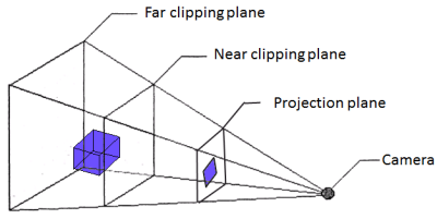
Screen space has Z=0 at the camera position. The Z value you want for your unproject will be a value between the near and far plane values you have in your viewport, as this is the visible range of objects in the camera frustum. Z values outside this range will result in the object being clipped from view.
Try using a Z value that is slightly larger than your near plane. For example, if your near plane is at 1, try using 2 or 3. The Vector3 you would feed into the Unproject call would then be new Vector3(100, 100, 3).
I have been experimenting with many different numbers in the past 30 minutes.
When i try (100,100,1), it is drawn at (137,145) in the screen and the model is at least 2 times smaller than what it should be (with the view i am using right now).
Also, (200,200,1) is draw at (299,307) which is not even 2*(137,145) as it should be , right ? ( it is not even k*(100,100) ). I imagine that when you unproject (100,100,1) and (100,100, 1.01f) you should get (100,100) in “the screen space” in both cases.
Also, when i use 0.99f or 1.01f or 2 or 3 it is completely outside screen range. My near plane is 1 and far plane is 10000.
Could it be i am doing this wrong ? All i did so far was change Project() to Unproject() and play with the new vector3(100, 100, 1) which i originally had
Now, I don’t think you really need to unproject your models by your own. Unless this is about drawing debug lines on an editor, you are just fine positioning your camera above that plane and call .Draw() on your brick model.
Use the unproject function only for picking object with mouse/touch.
How else would i draw things on (X,Y) then ? ts so much harder trying to play with view angle / model position to make everything get drawn in the right place. Also, later on, I will need to draw a 3D model on my cursor’s position, how would i do that then ?
“later on, I will need to draw a 3D model on my cursor’s position, how would i do that then ?”
keep in mind that a pixel in a 2D projection (the screen) transformed into 3D is equivalent to an “infinite” line in 3D space. In other words, imagine a window of your house, and a laser pointer pointing to that window. “What’s beyond the window” (3D space) is an infinite line (the laser ray), not a point.
There’s no such “cursor position” in 3D (it’s a “cursor line”, or the laser ray) unless you specify an extra parameter (depth)
In example, if you want to pick an object beyond the window, you can calculate Unproject for Z=0 and then Unproject for Z=1. That will give you the “cursor line” (or the laser ray) at the point of the screen you desire.
Then, you can detect which bounding box (or plane) of that object is colliding with that line.
As the arkanoid bricks will be over a plane (the background), that would be the place to use to collide with the laser line.
However, maybe you’re doing the things “the wrong way”. I mean, people that usually
wants to mix 2D and 3D stuff, uses a 3D “base” and adds 2D items projecting from 3D to 2D. That is way easier because you don’t have to invent depth values. Projection from 3D to 2D already contains all the information.
It’s not that it can’t be done, it’s just that it’s way easier this way, specially if you’re beginning with it.
I am not sure you completely understand the situation, so i will explain it hopefully better. Say i want to draw one brick at (0,200) on my screen. Since i already have the effect.View and the effect.Projection already set (which effectively defines the size of the brick on my screen (about 72pixels width on each brick cause i have 10 bricks in each line and a 720pixels wide “screen”)) i need a vector3 modelPosition with the location that i will draw it.
So it all comes down to the following problem: calculating the modelPosition so that the brick will be draw at (0,200) on the screen. So that i will set the only thing missing, the effect.World, which needs requires Matrix.CreateTranslation(modelPosition)
The method i was using before, was testing it many many times, and come up with those “magic” numbers like modelPosition = new Vector3(-1350, 1795, 0); And that would draw the model at something like (0,200). So to fill a row, i would do a for loop with modelPosition = new Vector3(-1350 * (i * 300) , 1795, 0);, 300 is another “magic number” which is the brick’s width apparently.
So instead of this painful procedure i found out you can do graphics.GraphicsDevice.Viewport.Unproject and calculate the actual modelPosition from a point in the screen like (0,200). Which is exactly what i am trying to do.
What exactly are you suggesting ? Can you post some relative code ? The example i have above is only 10 lines long and the numbers are easy. I am not in the state that i can translate english words about 3D to code. I have been solely programming in 2D so far.
This really is the backwards way of doing it. Why not position your bricks in world space, where you know the exact dimensions of each brick, and then set your View and Projection matrices such that all the bricks are positioned correctly? By world-space, I mean that if each brick is 1m cubed, then the modelPosition of each brick will be 1m away from it’s neighbours.
However, assuming you really do need to set your brick positions based on screen space (for some unexplained reason), you should follow KakCAT’s advice. Get two world points using Unproject twice using depth of 0 and 1. The first will be a point on the near plane and the second will be on the far plane. Then, get a normalized ray, something like Vector3 ray = Vector3.Normalize(farPos - nearPos). Then, you’d use something like modelPosition = cameraPos + depth * ray. So, the next question is how to calcuate the required depth value (or model scale value) such that your bricks line up together. Too small and they will overlap, too large and there will be gaps. The calculation will depend on your Projection matrix. If you camera doesn’t move, you can probably use trial and error to come up with a constant depth that works for your particular brick size though.
As you can see, it’s much easier to work in world-space. Hope that helps!
In that method of calculating the brick position based on screen space, where is the screen space involved ? for example a point (0,200). You said i unproject two world points (how do i get those ?), and then depending of the depth i use, the brick’s position varies ? This method sounds a bit vague when my question is pretty straight forward. What i am trying to do is explained better if i asked “how to draw a 3D model centered on mouse cursor’s position?”.
Your example point is in screen space, ie a pixel position. To understand how to Unproject a screen space point to a world space ray, please carefully read this: XNA Game Studio 4.0 Refresh | Microsoft Learn
if you ask “how to draw a 3D model centered on mouse cursor’s position?”, you will still have the same problem - the mouse position on your 2D screen corresponds to a ray (ie a line) in 3D. How far along that line do you want the model to be drawn? This is the depth I was talking about.
Forget about pixels, first you have to model your world. Figuring out how to render it is last. Modeling your world after pixels is posible but not very helpful, you would need to scale that to render on different resolutions anyway. Whether you write your own physics or use an existing engine you will definitly work with KMS units. (Kilo, Meter, Second).
So, define your bricks in meters (2x1x1) and position them as Vector3((col * 2) , row, 0). For simplicity Map 2D space to 3D space as [X,Y,0] (ignore the Z dimension). All you have to worry now is positioning your camera to the right distance to ‘see’ all the bricks and the rocket. Position it a few meters Backward and make it face forward (LookAt=[0,0,0], Up = Vector3.Up).
How big a brick would appear depends on the camera distance, FieldOfView, and the actual resolution/dpi. Because of 3D distortion not all bricks appear the same.
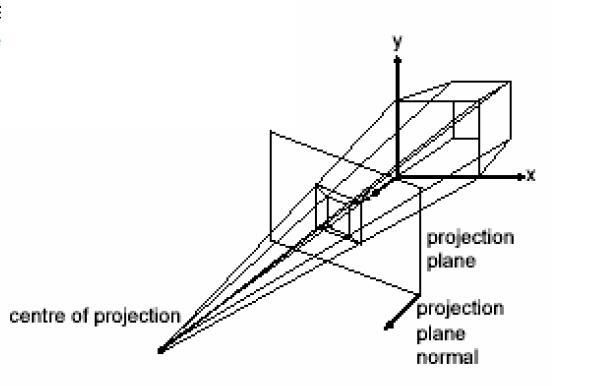
the perspectiveprojection that as described above
is not always desirable
in some case’s such as you described, it may not be
in that case a orthographicprojection maybe preferable that does not have parallax properties
Once you get the hang of it, using code to place objects in 3D and positioning a perspective camera to view them is easy enough. If you have one brick visible on the screen, you’re nearly there: wrap your mesh.Draw() (and effect.World = matrixTranslation) calls in two loops, one for horizontal bricks and one for vertical bricks. Then just change the modelPosition’s X and Y components based on your loop variables. This is almost exactly what @nkast suggested above:
        int columns = 5;
        int rows = 10;
        float depthZ = 5.0f;
        for (int i = 1; i < columns; i++)
        {
            for (int j = 0; j < rows; j++)
            {
                // You'll need to offset this, or offset the camera position to get it in the middle of the screen
                var modelPosition = new Vector3(i * 2, j, depthZ);
                effect.World = Matrix.CreateScale(Scale) * Matrix.CreateTranslation(modelPosition);

                //finally i draw the model
                mesh.Draw();
            }
        }
the 3d perspective approach maybe easier or not
depending on how you look at it
im definitely not saying orthographic is better, just that it is different yet useable
i might argue mathematically its more efficient
but
the below quote is not entirely true
Keep in mind though, if you go for orthographic projection, your 3D
brick models will look 2D, ie you’ll not be able to see the sides at
all.
please note that spritebatch accepts a matrice as well as any effect has access to alter the view matrix
as well as any model can be drawn at a angle to show its sides
perspective projection essentially draws farther vertices closer to the center of screen warping the appearance of there x y positions
often cad type programs and editors will use orthographic projection just fine to see the sides of 3d models or surfaces
what is normally done under orthographic projection
is that the view matrix is set up to be slightly off angle this means the view camera should have some extra background around the game board or some padding around the 2d ground ect…
in addition this means when rotating the camera if that is added
the cameras position may want to spin around some additional orbital center camera position and its to target should remain the same spot on the map
or
but less preferable for a very simple 2d game each models world matrix has a little y or x rotation added and a little z rotation as wel to draw them slightly off angle so that the models sides are seen as well
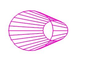
further on perspective understand
essentially this is (3d + distance based xy position warping to screen)
to say in the image of perspective that is the effect mathematically of the projection matrice
though the reverse of what is shown is done to vertices in translation to the screen
mathematically things at the far plane are shrunk to screen more so then things at the near plane which are fitted directly to the screen
so to imagine in your mind how that works
you would look at that perspective cone somewhat in reverse and further, reverse the near and far planes to see the ratio of shrinking
in order to imagine what perspective projection does to vertices of models according to their z depth
this is why the unproject is required to reverse that warping
further know,
what the projection matrix does is not the same as real life perspective, were in.
things at distance do not shrink, its that our eye lens are curved
so edges at further distance, have a different parallax view at distance
remember we have two eyes these give us a slight parallax view
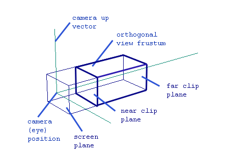
orthographic -
simply projects vertices to screen without any xy distortion due to depth and no curved eye lens
however if the side of a object is visible it will be shown
its like the screen itself flattens out and widens your eye lens and lets you look directly into a box with objects in it
you see the sides of objects dependent on if they are facing your view or not,
this box maybe moved around with the object inside unmoving
 thanks