2D Vertex Transformations Help?

Hi Monogame,

I am working on a simple 2D Graphics Library for games. It has worked in previous versions but I am currently having a subtle bug problem.

I want points specified in drawing methods to correspond directly to traditional screen pixel coordinates. So, let’s say a screen is 1024 x 768. I want my DrawBox method to take a Rectangle as a parameter (e.g. 0, 0, 1024, 768) and the box to be drawn around the edge pixels of the screen.

My drawbox method uses a linestrip to draw the box, and the results seem to be slightly off. In 1920 x 1080 resolution, for example, the origin 0, 0 is off the screen, and point 1919, 1079 is not the bottom right. So a box the size of the screen is shown missing the top and left boundary lines.

This is the code that sets up the standard BasicEffect used for the transformations -

        // Create a convenient coordinate transformation matrix.
        screenTransformMatrix = Matrix.CreateScale (2f / (float) surfaceWidth, -2f / (float) surfaceHeight, 0) * Matrix.CreateTranslation (-1, 1, 0);
        surfaceTransformMatrix = screenTransformMatrix;

[…]

        // This is a 2 dimensional graphics engine. No matrix transformations on points are desirable.
        standardEffect.Projection = Matrix.Identity;
        // Automatically transform surface points to render points.
        standardEffect.View = surfaceTransformMatrix;
        standardEffect.World = Matrix.Identity;

        // Standard effect basic settings.
        standardEffect.Alpha = 1;
        standardEffect.TextureEnabled = false;
        standardEffect.VertexColorEnabled = true;

I am worried it is slightly incorrect?

This is the code that draws the box -

        boxArray [0] = new VertexPositionColorTexture (new Vector3 (box.Left, box.Top, 0), lineColour, new Vector2 (0, 0));
        boxArray [1] = new VertexPositionColorTexture (new Vector3 (box.Right - 1, box.Top, 0), lineColour, new Vector2 (0, 0));
        boxArray [2] = new VertexPositionColorTexture (new Vector3 (box.Right - 1, box.Bottom - 1, 0), lineColour, new Vector2 (0, 0));
        boxArray [3] = new VertexPositionColorTexture (new Vector3 (box.Left, box.Bottom - 1, 0), lineColour, new Vector2 (0, 0));
        boxArray [4] = boxArray [0];

        lock (synchronisationObject)
        {
            // Set texture addressing to clamp mode.
            outputDevice.BlendState = BlendState.AlphaBlend;
            outputDevice.SamplerStates [0] = SamplerState.PointClamp;

            // Render the box.
            standardEffect.Alpha = (float) lineColour.A / 255f;
            standardEffect.TextureEnabled = false;
            standardEffect.CurrentTechnique.Passes [0].Apply ();
            outputDevice.DrawUserPrimitives<VertexPositionColorTexture> (PrimitiveType.LineStrip, boxArray, 0, 4);
        }

I get the impression the problem is with the translation. The resulting boxes are also missing the top left pixel when looked at on screen…
What is your projection matrix?
If you want the same projection as SpriteBatch:

var viewport = GraphicsDevice.Viewport;
Matrix projectionMatrix = Matrix.CreateTranslation(-0.5f, -0.5f, 0) * Matrix.CreateOrthographicOffCenter(0, viewport.Width, viewport.Height, 0, 0, -1);

Below is the code that creates the transformations used in my effect. I tried the one you suggested but it behaved exactly the same as the one I am using. As I said, my goal is pixel accuracy, so (0,0) in my coordinate system should be (0,0) on screen, and e.g. (1023, 767) should be the bottom right (or for example 1279, 1023 as screen resolutions vary).

screenTransformMatrix = Matrix.CreateScale (2f / (float) surfaceWidth, -2f / (float) surfaceHeight, 0) * Matrix.CreateTranslation (-1, 1, 0);
standardEffect.Projection = Matrix.Identity;
// Automatically transform surface points to render points.
standardEffect.View = surfaceTransformMatrix;
standardEffect.World = Matrix.Identity;

Am I using the wrong translation to achieve my goal?

Okay I added a pixel adjustment of one pixel, but now the bottom right pixel of my boxes is not drawing.

Ah, you original did post your projection matrix. Well, that assumption is wrong. A projection matrix using Matrix.Identity is not going to work. The chain of matrix transformations to transform vertices from model space to world space, then from world space to view space, and then finally from view space to projection space (World * View * Projection) is one of the details of the rendering pipeline for any game. Wether the game is 3D or 2D is irrelevant since MonoGame uses the 3D API for OpenGL / DirectX. However, 2D is just a special case of 3D, thus an orthographic projection can be used for 2D games that collapses the the 3D scene into a 2D scene with no depth perception. This is exactly what the beloved SpriteBatch does; the transformMatrix parameter for SpriteBatch.Begin() is just an opportunity to apply a view matrix to the generated projection matrix handled by SpriteBatch.

A Matrix.Identity and an orthographic projection result in the same transformation? What effect are you using?

My bad. I had my matrix transformation in ‘View’ not Projection, but because the other two transformations were Identity matrices it had the same effect. I have corrected the code -

standardEffect.Projection = Matrix.CreateScale (2f / (float) surfaceWidth, -2f / (float) surfaceHeight, 0) * Matrix.CreateTranslation (-1, 1, 0);

This is directly equivalent to writing -

Matrix.CreateOrthographicOffCenter(0, viewport.Width, viewport.Height, 0, 0, -1);

And in fact if you convert the resulting Matrix.ToString() the fields are all the same.

I then added -

*= Matrix.CreateTranslation (0.5f * screenTransformMatrix.M11, 0.5f * screenTransformMatrix.M22, 0);

This had the effect of adding a half pixel correction to the transformation.

Now my boxes display pixel perfectly except that the very bottom right corner pixel of the box is not showing when rendered using a LineStrip or a LineList.

For an outline of a rectangle? Try using alternating starting vertices for the lines in clockwise fashion.

You want (1920-1) translated into (1024-1=1023).
I imagine it’s a rounding error that result into a value between 1023.0 and 1024.0. Then the GPU round() or ceil() that value up to 1024.
What do you get if you multiply the projMatrix with Vector2(1023,767) ?

Here’s what i get.

            var proj = Matrix.CreateOrthographicOffCenter(0, 1024, 768, 0, 0, -1);
            proj *= Matrix.CreateTranslation (0.5f * proj.M11, 0.5f * proj.M22, 0);
            var v = new Vector2(1023, 767);
            var projv = Vector2.Transform(v, proj); //  = (0.9990234,-0.9986979)
            var screenv = projv * new Vector2(1919, 1079); // = (1917.126,-1077.595)

            var proj2 = Matrix.CreateOrthographicOffCenter(0, 1920, 1080, 0, 0, -1);
            proj2 *= Matrix.CreateTranslation(0.5f * proj.M11, 0.5f * proj.M22, 0);
            var v2 = new Vector2(1919, 1079);
            var projv2 = Vector2.Transform(v2, proj2); //  = (0.999935,-0.9994501)
            var screenv2 = projv2 * new Vector2(1919, 1079); // = (1918.875,-1078.407)

Okay. A rounding error looks plausible. What solution do you suggest (if any) to correct it?

The code I posted suggests that there shouldn’t be a problem. Can you post the final code?
What platform are you using? DX/GL? I think only GL needs the halfpixel.
I you draw for example at (1022, 766) do you see the bottom right line?

I am using the Monogame 3.5 Windows platform with DX. Just to be clear, in case I was not earlier, I am not trying to translate between 1024x768 and 1920x1080 just they are alternative modes I am testing in.

so -

screenTransformMatrix = Matrix.CreateScale (2f / (float) surfaceWidth, -2f / (float) surfaceHeight, 0) * Matrix.CreateTranslation (-1, 1, 0);
screenTransformMatrix *= Matrix.CreateTranslation (0.5f * screenTransformMatrix.M11, 0.5f * screenTransformMatrix.M22, 0);
surfaceTransformMatrix = screenTransformMatrix;

standardEffect.Projection = surfaceTransformMatrix;
standardEffect.View = Matrix.Identity;
standardEffect.World = Matrix.Identity;
standardEffect.Alpha = 1;
standardEffect.TextureEnabled = false;
standardEffect.VertexColorEnabled = true;

and in the drawing method …
(assume box left is 0, top is 0, bottom is 768 and right is 1024)

boxArray = new VertexPositionColorTexture [5];
boxArray [0] = new VertexPositionColorTexture (new Vector3 (box.Left, box.Top, 0), lineColour, new Vector2 (0, 0));
boxArray [1] = new VertexPositionColorTexture (new Vector3 (box.Right - 1, box.Top, 0), lineColour, new Vector2 (0, 0));
boxArray [2] = new VertexPositionColorTexture (new Vector3 (box.Right - 1, box.Bottom - 1, 0), lineColour, new Vector2 (0, 0));
boxArray [3] = new VertexPositionColorTexture (new Vector3 (box.Left, box.Bottom - 1, 0), lineColour, new Vector2 (0, 0));
boxArray [4] = boxArray [0];

outputDevice.BlendState = BlendState.AlphaBlend;
outputDevice.SamplerStates [0] = SamplerState.PointClamp;
standardEffect.Alpha = (float) lineColour.A / 255f;
standardEffect.TextureEnabled = false;
standardEffect.CurrentTechnique.Passes [0].Apply ();
outputDevice.DrawUserPrimitives (PrimitiveType.LineStrip, boxArray, 0, 4);

Oh, I see.
So, have you tried without the halfpixel correction then?

Yes. See above.

The original problem was that everything was displaced by -1 pixel x and y. This is now solved by the half pixel adjustment. The new problem is that the bottom right corner pixel of rectangles is not drawing. The rectangle is implemented as a clockwise linestrip as above.

Are you sure? Perhaps it is CreateScale (2f / (float) surfaceWidth, -2f / (float) surfaceHeight, -1) or something like that to get an orthogonal matrix. You scale Z by 0. It might not have an effect but it’s worth to verify. Because clearly the only case where MG sets NeedsHalfPixelOffset is in GraphicsDevice.OpenGL.cs. You might been chasing the wrong problem.

You mean the Right Line and the Botton Line? right?
Or just a single pixel at the corner? In that case I 'll be very interested to a screenshot :astonished:

What happens is you disable depth/Culling?

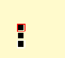
Just the pixel. Here is an example image from a screenshot.

The image should have a lemon-ish yellow background. That is ok. Then I try to draw three rectangles, placed under each other on the screen. The first is meant to be 10,10, with a red border and black fill. The next is meant to have a transparent border and black fill. The next a white border and black fill. You should probably use an image viewer that lets you zoom in.

Problems -

(1) The box borders are now correctly placed, to the pixel, except the bottom right corner pixel (and only that pixel) is missing.

(2) The fill is accomplished using two triangle strips. It is intended to be one pixel smaller in all dimensions than the border. It is two pixels smaller at the bottom right. Oddly, the bottom right pixel is not missing.

I tired to test your code and i don’t see it. Have you tried it on another PC?
BTW, indeed, the halfpixeloffset seems to be required.

Yes. I worked out the triangle fill problem. See what happens if we put the rasterizer into wireframe mode changing nothing else -

Suddenly the lines are flush, although the bottom right corner is missing. Whilst in fill mode the edges are not. Why? Well we do the half pixel adjustment with lines because the points in our mathematical world space are the edges of our pixel space. So we put our points for lines in the middle of pixels.

When we draw lines it draws accordingly, but when we do a fill, it fills INSIDE the plotted area. So we want the edges of pixels. If you go back to fill mode and adjust the triangle edges accordingly the fill works.

That just leaves the missing pixel on the lines.

… and the missing pixel was a similar issue causing the right most and lowest point of lines not to draw (tried drawing each point on the line one at a time.

All solved. Thanks for looking at it for me.