Hi! I was trying to add a CRT shader to my game, but after applying that effect to my SpriteBatch, it stops taking into account the color tints that I pass in to my Draw() calls. Is there something I’m missing? Here are some code snippets:
The SpriteBatch call before everything in my game is drawn:
_spriteBatch.Begin(SpriteSortMode.BackToFront, BlendState.AlphaBlend, SamplerState.PointWrap, null, null, CRTEffect, Globals.Camera.TranslationMatrix);
Example of tinting (this is done to grey out tiles that aren’t in your field of view):
spriteBatch.Draw(floorTex, position, null, Color.Gray, 0.0f, Vector2.Zero, new Vector2(scale, scale), SpriteEffects.None, LayerDepth.Cells);
The shader code (found online)
#if OPENGL
	#define SV_POSITION POSITION
	#define VS_SHADERMODEL vs_3_0
	#define PS_SHADERMODEL ps_3_0
#else
	#define VS_SHADERMODEL vs_4_0_level_9_1
	#define PS_SHADERMODEL ps_4_0_level_9_1
#endif
/* --- Settings --- */

#define CRTAmount            0.4   //[0.00 to 1.00]  Amount of CRT effect you want

#define CRTResolution        1.0     //[1.0 to 8.0]    Input size coefficent (low values gives the "low-res retro look"). Default is 1.2
#define CRTgamma             3.0     //[0.0 to 4.0]    Gamma of simulated CRT (default 2.2)
#define CRTmonitorgamma      3.0     //[0.0 to 4.0]    Gamma of display monitor (typically 2.2 is correct)
#define CRTBrightness        3.0     //[1.0 to 3.0]    Used to boost brightness a little. Default is 1.0
#define CRTScanlineIntensity 4.0     //[2.0 to 4.0]    Scanlines intensity (use integer values preferably). Default is 2.0
#define CRTScanlineGaussian  0       //[0 or 1]        Use the "new nongaussian scanlines bloom effect". Default is on

#define CRTCurvature         0       //[[0 or 1]          "Barrel effect" enabled (1) or off (0)
#define CRTCurvatureRadius   2.0     //[0.0 to 2.0]       Curvature Radius (only effective when Curvature is enabled). Default is 1.5
#define CRTCornerSize        0.0100  //[0.0000 to 0.0020] Higher values, more rounded corner. Default is 0.001
#define CRTDistance          4.00    //[0.00 to 4.00]     Simulated distance from viewer to monitor. Default is 2.00
#define CRTAngleX            0.00    //[-0.20 to 0.20]    Tilt angle in radians (X coordinates)
#define CRTAngleY           -0.15   //[-0.20 to 0.20]    Tilt angle in radians (Y coordinates). (Value of -0.15 gives the 'arcade tilt' look)
#define CRTOverScan          1.00    //[1.00 to 1.10]     Overscan (e.g. 1.02 for 2% overscan). Default is 1.01
#define CRTOversample        0       //[0 or 1]           Enable 3x oversampling of the beam profile (warning : performance hit)


/* ---  Defining Constants --- */
#define myTex2D(s,p) tex2D(s,p)

#ifndef s0
sampler s0 : register(s0);
#define s1 s0
//sampler s1 : register(s1);

float4 p0 : register(c0);
float4 p1 : register(c1);

//  #define width (p0[0])
//  #define height (p0[1])
//  #define counter (p0[2])
//  #define clock (p0[3])
//  #define px (p1[0]) //one_over_width
//  #define py (p1[1]) //one_over_height

#define px (p1.x) //one_over_width
#define py (p1.y) //one_over_height

#define screen_size float2(p0.x,p0.y)

#define pixel float2(px,py)

  //#define pxy float2(p1.xy)

  //#define PI acos(-1)
#endif


/* ---  Main code --- */

// CRT shader
//
// Copyright (C) 2010-2012 cgwg, Themaister and DOLLS
//
// This program is free software; you can redistribute it and/or modify it
// under the terms of the GNU General Public License as published by the Free
// Software Foundation; either version 2 of the License, or (at your option)
// any later version.

#define d CRTDistance
#define R CRTCurvatureRadius

// Comment the next line to disable interpolation in linear gamma (and gain speed).
//#define LINEAR_PROCESSING

// aspect ratio
#define aspect float2(1.0, 0.75)

// Precalculate a bunch of useful values we'll need in the fragment
// shader.
#define sinangle sin(float2(CRTAngleX, CRTAngleY))
#define cosangle cos(float2(CRTAngleX, CRTAngleY))
#define stretch maxscale()

// Macros.
#define FIX(c) max(abs(c), 1e-5);

float PI = acos(-1); //#define PI 3.141592653589

// The size of one texel, in texture-coordinates.
#define coone 1.0 / rubyTextureSize

#define mod_factor tex.x * rubyTextureSize.x * rubyOutputSize.x / rubyInputSize.x

#ifdef LINEAR_PROCESSING
#define TEX2D(c) pow(myTex2D(s0, (c)), CRTgamma)
#else
#define TEX2D(c) myTex2D(s0, (c))
#endif

float intersect(float2 xy)
{
    float A = dot(xy, xy) + (d * d);
    float B = 2.0 * (R * (dot(xy, sinangle) - d * cosangle.x * cosangle.y) - d * d);
    float C = d * d + 2.0 * R * d * cosangle.x * cosangle.y; //all constants
    return (-B - sqrt(B * B - 4.0 * A * C)) / (2.0 * A);
}


float2 bkwtrans(float2 xy)
{
    float c = intersect(xy);
    float2 _point = float2(c, c) * xy;
    _point -= float2(-R, -R) * sinangle;
    _point /= float2(R, R);
    float2 tang = sinangle / cosangle;
    float2 poc = _point / cosangle;
    float A = dot(tang, tang) + 1.0;
    float B = -2.0 * dot(poc, tang);
    float C = dot(poc, poc) - 1.0;
    float a = (-B + sqrt(B * B - 4.0 * A * C)) / (2.0 * A);
    float2 uv = (_point - a * sinangle) / cosangle;
    float r = R * acos(a);
    return uv * r / sin(r / R);
}

float2 fwtrans(float2 uv)
{
    float r = FIX(sqrt(dot(uv, uv)));
    uv *= sin(r / R) / r;
    float x = 1.0 - cos(r / R);
    float D = d / R + x * cosangle.x * cosangle.y + dot(uv, sinangle);
    return d * (uv * cosangle - x * sinangle) / D;
}

float3 maxscale()
{
    float2 c = bkwtrans(-R * sinangle / (1.0 + R / d * cosangle.x * cosangle.y));
    float2 a = float2(0.5, 0.5) * aspect;
    float2 lo = float2(fwtrans(float2(-a.x, c.y)).x,
		             fwtrans(float2(c.x, -a.y)).y) / aspect;
    float2 hi = float2(fwtrans(float2(+a.x, c.y)).x,
		             fwtrans(float2(c.x, +a.y)).y) / aspect;
    return float3((hi + lo) * aspect * 0.5, max(hi.x - lo.x, hi.y - lo.y));
}

float2 transform(float2 coord, float2 textureSize, float2 inputSize)
{
    coord *= textureSize / inputSize;
    coord = (coord - 0.5) * aspect * stretch.z + stretch.xy;
    return (bkwtrans(coord) / float2(CRTOverScan, CRTOverScan) / aspect + 0.5) * inputSize / textureSize;
}

float corner(float2 coord, float2 textureSize, float2 inputSize)
{
    coord *= textureSize / inputSize;
    coord = (coord - 0.5) * float2(CRTOverScan, CRTOverScan) + 0.5;
    coord = min(coord, 1.0 - coord) * aspect;
    float2 cdist = float2(CRTCornerSize, CRTCornerSize);
    coord = (cdist - min(coord, cdist));
    float dist = sqrt(dot(coord, coord));
    return clamp((cdist.x - dist) * 1000.0, 0.0, 1.0);
}

// Calculate the influence of a scanline on the current pixel.
//
// 'distance' is the distance in texture coordinates from the current
// pixel to the scanline in question.
// 'color' is the colour of the scanline at the horizontal location of
// the current pixel.
float4 scanlineWeights(float distance, float4 color)
{
  // "wid" controls the width of the scanline beam, for each RGB channel
  // The "weights" lines basically specify the formula that gives
  // you the profile of the beam, i.e. the intensity as
  // a function of distance from the vertical center of the
  // scanline. In this case, it is gaussian if width=2, and
  // becomes nongaussian for larger widths. Ideally this should
  // be normalized so that the integral across the beam is
  // independent of its width. That is, for a narrower beam
  // "weights" should have a higher peak at the center of the
  // scanline than for a wider beam.
#if CRTScanlineGaussian == 0
	float4 wid = 0.3 + 0.1 * pow(color, 3.0);
	float4 weights = float4(distance / wid);
	return 0.4 * exp(-weights * weights) / wid;
#else
    float4 wid = 2.0 + 2.0 * pow(color, 4.0);
    float calcdistance = distance / 0.3; // Optimization  ?
    //float4 weights = float4(distance / 0.3, distance / 0.3, distance / 0.3, distance / 0.3);
    float4 weights = float4(calcdistance, calcdistance, calcdistance, calcdistance);
    return 1.4 * exp(-pow(weights * rsqrt(0.5 * wid), wid)) / (0.6 + 0.2 * wid);
#endif
}

float4 AdvancedCRTPass(float4 colorInput, float2 tex)
{
	// Here's a helpful diagram to keep in mind while trying to
	// understand the code:
	//
	//  |      |      |      |      |
	// -------------------------------
	//  |      |      |      |      |
	//  |  01  |  11  |  21  |  31  | <-- current scanline
	//  |      | @    |      |      |
	// -------------------------------
	//  |      |      |      |      |
	//  |  02  |  12  |  22  |  32  | <-- next scanline
	//  |      |      |      |      |
	// -------------------------------
	//  |      |      |      |      |
	//
	// Each character-cell represents a pixel on the output
	// surface, "@" represents the current pixel (always somewhere
	// in the bottom half of the current scan-line, or the top-half
	// of the next scanline). The grid of lines represents the
	// edges of the texels of the underlying texture.

    float Input_ratio = ceil(256 * CRTResolution);
    float2 Resolution = float2(Input_ratio, Input_ratio);
    float2 rubyTextureSize = Resolution;
    float2 rubyInputSize = Resolution;
    float2 rubyOutputSize = screen_size;

#if CRTCurvature == 1
    float2 xy = transform(tex, rubyTextureSize, rubyInputSize);
#else
    float2 xy = tex;
#endif
    float cval = corner(xy, rubyTextureSize, rubyInputSize);

    // Of all the pixels that are mapped onto the texel we are
    // currently rendering, which pixel are we currently rendering?
    float2 ratio_scale = xy * rubyTextureSize - 0.5;

#if CRTOversample == 1
	float filter = fwidth(ratio_scale.y);
#endif
    float2 uv_ratio = frac(ratio_scale);

    // Snap to the center of the underlying texel.
    xy = (floor(ratio_scale) + 0.5) / rubyTextureSize;

	// Calculate Lanczos scaling coefficients describing the effect
	// of various neighbour texels in a scanline on the current
	// pixel.
    float4 coeffs = PI * float4(1.0 + uv_ratio.x, uv_ratio.x, 1.0 - uv_ratio.x, 2.0 - uv_ratio.x);

	// Prevent division by zero.
    coeffs = FIX(coeffs);

	// Lanczos2 kernel.
    coeffs = 2.0 * sin(coeffs) * sin(coeffs / 2.0) / (coeffs * coeffs);

	// Normalize.
    coeffs /= dot(coeffs, 1.0);

	// Calculate the effective colour of the current and next
	// scanlines at the horizontal location of the current pixel,
	// using the Lanczos coefficients above.
    float4 col = clamp(mul(coeffs, float4x4(
			TEX2D(xy + float2(-coone.x, 0.0)),
			TEX2D(xy),
			TEX2D(xy + float2(coone.x, 0.0)),
			TEX2D(xy + float2(2.0 * coone.x, 0.0)))),
			0.0, 1.0);
    float4 col2 = clamp(mul(coeffs, float4x4(
			TEX2D(xy + float2(-coone.x, coone.y)),
			TEX2D(xy + float2(0.0, coone.y)),
			TEX2D(xy + coone),
			TEX2D(xy + float2(2.0 * coone.x, coone.y)))),
			0.0, 1.0);

#ifndef LINEAR_PROCESSING
    col = pow(col, CRTgamma);
    col2 = pow(col2, CRTgamma);
#endif

	// Calculate the influence of the current and next scanlines on
	// the current pixel.
    float4 weights = scanlineWeights(uv_ratio.y, col);
    float4 weights2 = scanlineWeights(1.0 - uv_ratio.y, col2);

#if CRTOversample == 1
    uv_ratio.y = uv_ratio.y + 1.0 / 3.0 * filter;
    weights = (weights + scanlineWeights(uv_ratio.y, col)) / 3.0;
    weights2 = (weights2 + scanlineWeights(abs(1.0 - uv_ratio.y), col2)) / 3.0;
    uv_ratio.y = uv_ratio.y - 2.0 / 3.0 * filter;
    weights = weights + scanlineWeights(abs(uv_ratio.y), col) / 3.0;
    weights2 = weights2 + scanlineWeights(abs(1.0 - uv_ratio.y), col2) / 3.0;
#endif

    float3 mul_res = (col * weights + col2 * weights2).rgb * float3(cval, cval, cval);

	// dot-mask emulation:
	// Output pixels are alternately tinted green and magenta.
    float3 dotMaskWeights = lerp(float3(1.0, 0.7, 1.0),
                                 float3(0.7, 1.0, 0.7),
                                 floor(mod_factor % CRTScanlineIntensity));

    mul_res *= dotMaskWeights * float3(0.83, 0.83, 1.0) * CRTBrightness;

	// Convert the image gamma for display on our output device.
    mul_res = pow(mul_res, 1.0 / CRTmonitorgamma);

	//return saturate(lerp(colorInput, float4(mul_res, 1.0), CRTAmount));
    colorInput.rgb = lerp(colorInput.rgb, mul_res, CRTAmount);
    return saturate(colorInput);
}

/* --- Main --- */

float4 MainPS(float2 tex : TEXCOORD0) : COLOR
{
    float4 c0 = tex2D(s0, tex);

    c0 = AdvancedCRTPass(c0, tex);

    return c0;
}
technique SpriteDrawing
{
    pass P0
    {
        PixelShader = compile PS_SHADERMODEL MainPS();
    }
};

#if SHADERed
#include "SHADERed/PS-DebugPatch.hlsl"
#include "SHADERed/PS-CoordinatesPatch.hlsl"
#endif
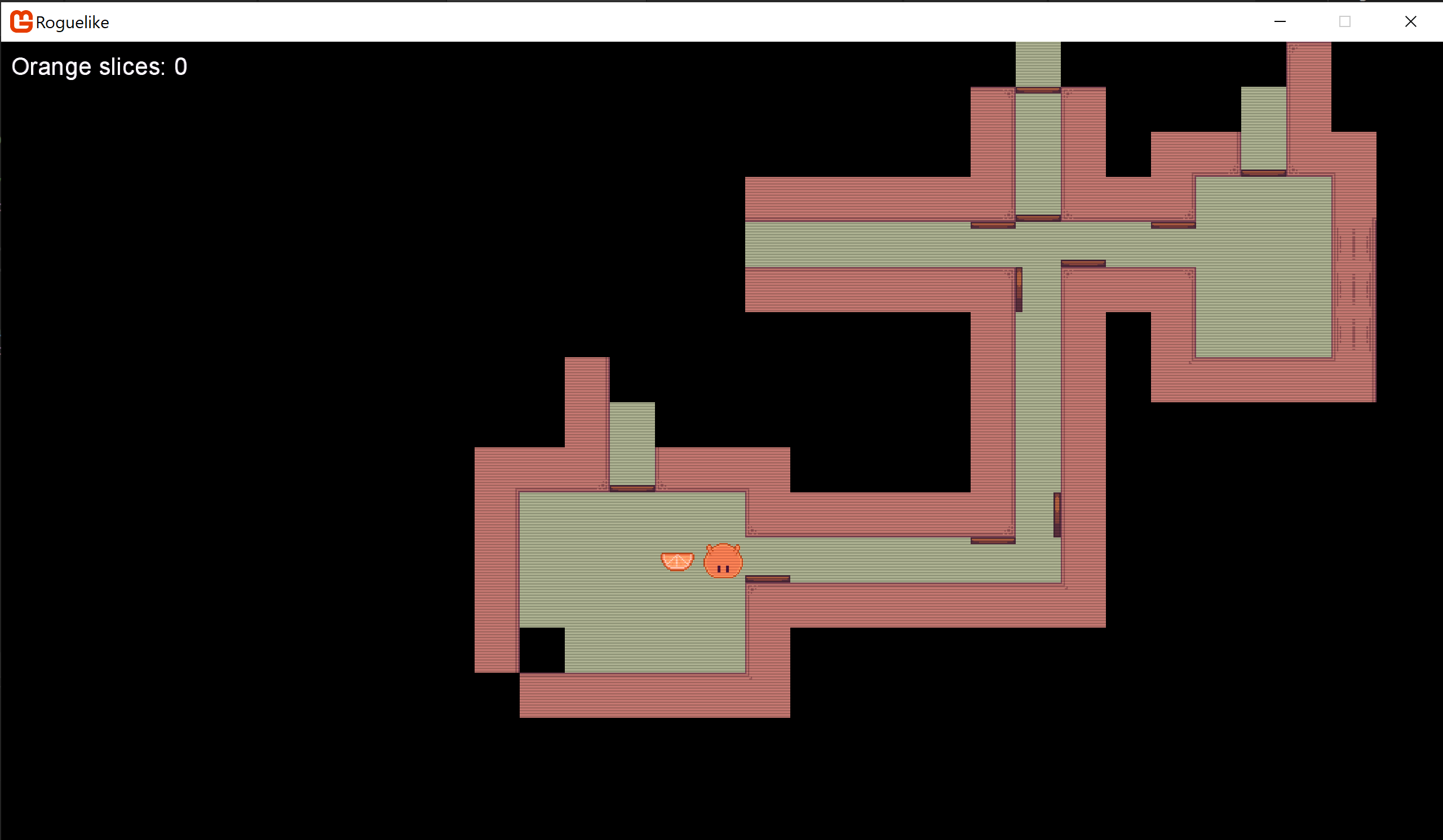
bonus screenshot ![]() (where tint isn’t working)
(where tint isn’t working)