Pixel-perfect image display

To whom it may assist:

I spent a good while repeatedly pondering and revising a way to place an image on the screen with pixel-perfect precision, and, after finally succeeding, I thought I might write a guide in light of the many pitfalls I encountered along the way.

For what it’s worth, for my purpose, I was trying to layer a pre-rendered image atop another render (think post-processing effects). In some cases, this might come out just fine, whether because they were rendered with the same dimensions anyway, or because any error is negligible. However, this was not the case for me; I needed to pursue perfectly accurate placement, as the transferred image was appearing slightly down and to the right of the underlying render.

So, firstly, if you’ve been working in 3D graphics, you should know that the viewport has x coordinates of -1 to 1 from left to right, and y coordinates -1 to 1 from bottom to top. You should also know that texture coordinates, on the other hand, range 0 to 1 from left to right and top to bottom.

Now, what if I told you that those figures aren’t exactly so?

Perfecting the viewport
First, let’s look at how to place our polygons exactly into the viewport. Using vertex coordinates of -1 and 1 will get the job done dirtily, but if we’re going for precision, there are a few things we need to examine more closely.

As it turns out, the right edge of the viewport is not x=1. x=1 is actually one pixel off the right side. So, what is the proper x coordinate to use?

x=-1 is indeed the left edge, but, because we’re dealing with an even number of pixels (presumably), x=0 is not exactly in the centre, as there is no exact centre. Rather, x=0 begins the right half of the viewport.

So, with that in mind, let’s work out the relationship with a linear equation, where viewport x-coordinate -1 corresponds to pixel position 0 (the left edge), and 1 corresponds to w (the number of pixels across, even though this coordinate is actually one pixel off the right edge). What, then, is the proper value to get us one pixel to the left of 1?
Using the coordinate pairs (-1, 0) and (1, w), the linear function mapping texture coordinates to pixel coordinates is y = w/2 x + w/2. Therefore, to achieve a pixel coordinate of w-1:
w-1 = w/2 x + w/2
w/2 - 1 = w/2 x
(w/2 - 1) / (w/2) = x
1 - 1/(w/2) = x
x = 1 - 2/w
So, for example, if our viewport is 1280 pixels across, we want the right edge to correspond to pixel x-coordinate 1279, and therefore we would use a vertex x-coordinate of 0.9984375.

HOWEVER!

In practice, this still doesn’t work out. At this point, my polygon was now ending one pixel short of the right edge. What gives?
Well, it turns out that that figure above, 0.9984375, cannot be stored precisely in a 32-bit float, and as such, was getting rounded down. Therefore, we actually have to aim ever so slightly higher, so that it rounds down to the proper pixel position. Let’s instead shoot for a desired pixel coordinate of 1279.5 - only half a pixel short of 1 - which causes us to recalculate the equation above.
w - 1/2 = w/2 x + w/2
w/2 - 1/2 = w/2 x
(w/2 - 1/2) / (w/2) = x
1 - (1/2)/(w/2) = x
x = 1 - 1/w
This solution makes sense in that it’s 1/w short of 1, where 2/w (or 1/(w/2)) is one whole pixel.

So, finally, we find that, for a viewport width of 1280 pixels, we want a pixel vertex coordinate around 0.99921875. When the GPU goes to round this down to the nearest pixel, it will land on 1279, just as we would want.

This same philosophy applies to the y direction, in that the actual y=-1 is one pixel off the bottom of our screen, or -1 + 1/h. So, if my viewport is 720 pixels tall, I want my vertices to be located at y=1 and y=-0.9986111.

(Also mind that this strategy, with minor alterations, would be valid for placing vertices into any arbitrary pixel-perfect region of the viewport, such as for sprites or tiling, etc.)

Perfecting the texture coordinates
Now that we’ve got our geometry perfectly aligned with our viewport, we have to worry about the texture coordinates. Now, if you were trying this hastily, you would probably use texcoords 0-1 for both left-to-right and top-to-bottom. However, this too is a misunderstanding. See, texcoord 0 (for both x and y dimensions) is not the first pixel in the texture, but rather the seam where the texture wraps around. The same is true of texcoord 1. In fact, texcoords 0 and 1 are exactly the same point - the seam about which the image wraps. As such, if you sample that point, it will be a blend of the first and last pixels in that row/column. Instead, we want to step half a texture pixel forward from that, to get to the centre of that first pixel, so, +(1/2)/w or +1/(2w). If our texture is, say, 1024 pixels across, then we have to make our first texture coordinate .5/1024=1/2048=0.00048828125. (Note, this metric is now in terms of the texture resolution, as opposed to the destination viewport resolution that we used above when placing the vertices!)

So, now we’ve successfully established a vertex at pixel position 0 that will sample the exact centre of the leftmost texture pixel, but now we need pixel position viewport.w-1 to sample the exact centre of pixel texture.w-1 - that is, half a pixel forward of texture.w-1, so texture.w-1/2. (In my example, I want viewport pixel 1279 to sample texture pixel 1023.5.)

However, recall that that’s not where we placed our right-edge vertex; we put that at x=viewport.w-1/2! Whatever texcoord we associate with that vertex must correspond to that assigned point, x=viewport.w-1/2, even though it will be sampled from viewport pixel x=viewport.w-1.

I’ll make another linear equation, mapping pixel coordinate 0 to texture coordinate 1/(2w), and pixel coordinate viewport.w-1 to (texture.w-1/2)/texture.w, or 1-1/(2texture.w) (that is, half a pixel back from the right edge).
data points (0, 1/(2tw)) and (vw - 1, 1-1/(2texture.w))
tx = (1- 1/(2tw) - 1/(2tw)) / (vw - 1) vx + 1/(2tw)
tx = (1- 1/tw) / (vw - 1) vx + 1/(2tw)

Now substitute our hypothetical viewport pixel position (which, remember, is viewport.w - 1/2, where we placed the vertex) for vx:
tx = (1- 1/tw) * (vw - 1/2) / (vw - 1) + 1/(2tw)

Oof, that looks rather messy, doesn’t it? If you wish to comprehend what’s happening, perhaps you can look at it as a “lerp” function, extrapolating half a pixel beyond our original data points above.

So, if, as in my own example, I have a texture with a width of 1024 pixels and a viewport width of 1280, I want the texcoord for my vertex at pixel position 1279.5 to be (1 - 1/1024) * (1279.5) / 1279 + 1/2048, or 0.9999022674.

Putting it all together

I do hope that this explanation helps someone out there! Please comment if you have any questions or feedback. Cheers!

4 Likes

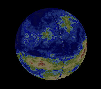
My apologies for responding to an old topic. This seemed at first to directly address a problem I’m having wrapping a texture around a 3D model (in this case a many faceted pseudo-sphere) where it appears there is a seam where u should wrap between 0 and 1.
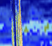
image
The texture is 1020 wide, so based on my sketchy understanding of your “perfecting the texture coordinates” description, I tried to force my u coordinates to fall exactly on a 1/1020 by changing the texture coordinate assignment from

(float)(Math.Atan2 (vpntWorld [intVertex].Position.Y / sngWorldRadius, vpntWorld [intVertex].Position.X / sngWorldRadius) / (Math.PI * 2.0) + 0.5)

to
(float)Math.Round ((float)(Math.Atan2 (vpntWorld [intVertex].Position.Y / sngWorldRadius, vpntWorld [intVertex].Position.X / sngWorldRadius) / (Math.PI * 2.0) + 0.5) * 1020) / 1020f;

Unfortunately I couldn’t get this, or any of a few variations on the theme, Floor, Ceiling, +1, etc., to change the visual result. I’m hoping that my error is obvious and grateful for any suggestions.

I ran into a similar issue when I was mapping a sphere, but it is unrelated to the topic above. Just in case this is your issue too, be sure that no triangles are defined between the two edges; you should have two lines of longitude - the “left” edge and the “right” edge" that overlap in space. Reason is, the left edge vertices will have a u coordinate of 0, and the right edge, although in the same spatial positions, will have a u coordinate of 1. For a sphere with n vertical strips, you will need n+1 vertices around, as the first and last will overlap. If these two extreme edges aren’t in the same place, and you try to index triangles between them, the texture coordinates in between will get interpolated in the 0-1 range. I predict what you’re seeing there is the entirety of your map, in reverse, along one longitudinal strip.

1 Like

@ed022, I think you’re spot-on with that assessment. I made that figure in a different program years ago by tessellating an octahedron and have since re-used it for this purpose having only to sort the vertices of each triangle clockwise to take advantage of culling the backside. It’s not immediately obvious to me how to achieve the overlap you’ve described, but I think that’s something I can probably figure out. Thanks very much!

@ed022, you were certainly correct about that strip of triangles interpolating the whole map in reverse. It’s quite clear in closeup:
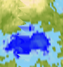
image
I’m halfway to solving it. I’m curious about the approach you took; would you mind sharing the details of your solution?
image

Ya that looks like your vertices are messed up not the texture.

You could extrude this PrimitiveCube.cs out to a sphere from the project below.
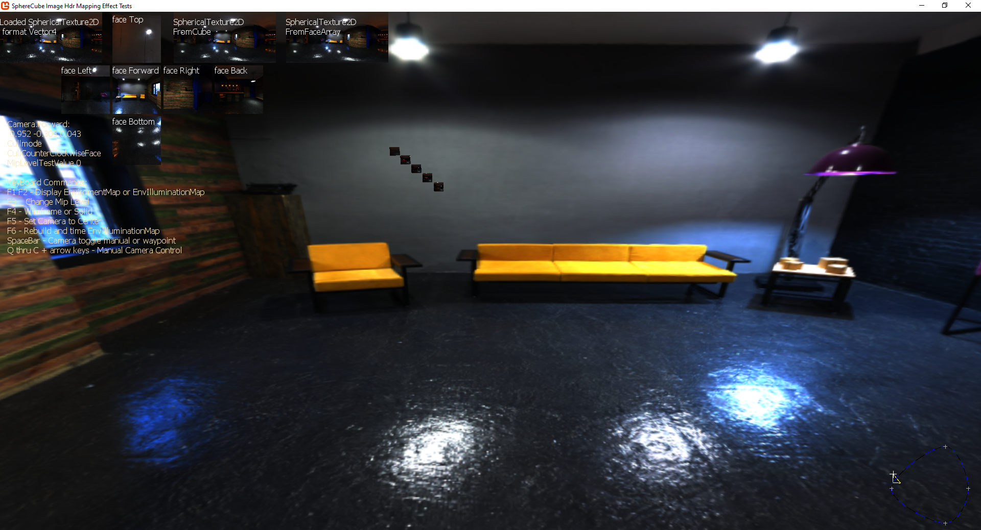
There is some nice functions as well in it and it can be used for regular textures as it converts between things. The edges are mapped correctly as seen in the image below.

Though in its entirety this project is still incomplete there is a shader problem that is unrelated to yours here in building a illumination map that i would love to get some help on as ive been stuck on it forever.

I have a tessellating sphere class as well, i could pull it out if you like, its very old i never cleaned it up it requires clamp to be used to get the edges just right and might actually be a pixel off or so. That is also a precision problem but more to do with vertice positioning and aliasing errors. I could post it up somewere if you like its extremely complicated i typically just use it for tests.

1 Like

The short version is how you create your vertex buffer. Suppose you want your sphere to have n strips of longitude, like the slices of a peeled orange. (From your picture, it looks like your “n” is quite high, like 100 or so.) You would need to allocate your vertex array to have n+1 vertices across. Part of your code might look like this:

for(int x = 0; x <= n; x++)
{
    double theta = 2 * Math.PI * x / n;
    vertex.Position.X = (float)Math.Cos(theta);
    vertex.Position.Z = -(float)Math.Sin(theta);
    vertex. TexCoord.X = (float)x / n;
}

Obviously, this is just an example. But the key that I want to point out is the <=. Note that, in the formula, when x is either 0 or n, the positions are the same, but the texture coordinate is 0 or 1, referring to the left seam and the right seam respectively.

1 Like

Thanks again, @ed022! You’re right, it would be 160 strips. Because of I how I constructed it, though, they’re not ordered in a helpful way and I don’t see a simple way for me to effectively doubly address or position one. That said, I can detect the condition where the wraparound happens by looking at the u range of the vertexes on a facet and correct it.

I’ve done this now, but missed a case as every other triangle along the “dateline” from the equator to the south pole does the whole-map-backwards thing, but the northern hemisphere is perfect.

Thanks, @willmotil! I’m certain that it’s the texture mapping rather than the vertexes, though. I originally used this set of primitives as VertexPositionColor array without problems. It was only after re-using the list as a VertexPositionNormalTexture (thanks for your write-up on that structure, by the way!) that I ran into this trouble. I can see that along the “international dateline” of my pseudo-sphere, there’s one line of facets running pole to pole that I initially assign a u range crossing 1 to 0 causing the texture mapping to pack every pixel at the facet’s latitude backwards into the one facet. I’m catching these now after I make the bad assignment and correcting them.

In case it helps any, here’s a more complete example.

int w = 160; // how many divisions around (longitude slices)
int h = 80; // how many divisions vertically (latitude slices)
//make a vertex buffer that is pretty much a tesslated square sheet - note that it is one vertex bigger than the geometry patches on each side
VertexPositionNormalTexture[] vbuf = new VertexPositionNormalTexture[(w + 1) * (h + 1)];
for(int y = 0; y <= h; y++)
{
    double pitch = Math.PI / 2 - y * Math.PI / h; // from pi/2 to -pi/2
    float radius = (float)Math.Cos(pitch);
    float height = (float)Math.Sin(pitch);
    for(int x = 0; x <= w; x++) // when x is either 0 or w, it'll be on the seam - different texcoords, but same position
    {
        VertexPositionNormalTexture v = new VertexPositionNormalTexture();
        double theta = x * 2 * Math.PI / w;
        v.Position = new Vector3(radius * (float)Math.Cos(theta), height, radius * -(float)Math.Sin(theta));
        v.TexCoord = new Vector2((float)x / w, (float)y / h);
        v.Normal = Vector3.Normalize(vbuf[index].Position);
        vbuf[y * (w + 1) + x] = v; // unique index into the vbuf
    }
}
//now link up the indices
int[] ibuf = new int[w * h * 6]; // w * h squares, each takes 6 indices
for(int x = 0; x < w; x++)
    for(int y = 0; y < h; y++)
    {
        int index = (y * w + x) + 6; // unique base index
        int vertex = y * (w + 1) + x; // base vertex
        ibuf[index + 0] = vertex;
        ibuf[index + 1] = vertex + 1; // one to the "right"
        ibuf[index + 2] = vertex + 1 + w + 1; // one right and down
        ibuf[index + 3]  = vertex + 1 + w + 1; // one right and down
        ibuf[index + 4] = vertex + w + 1; // one directly below;
        ibuf[index + 5] = vertex; // back to the original
    }
}

This is just off the top of my head, so I can’t guarantee it’ll work right out of the box, but the theory is all there.

1 Like

There is a easier way to do it.

Maybe ill make a simple sphere class out of that cube example and add it i need a new version anyways that is better then the old one i have which is over complicated.

So if you can’t get it sorted look to that example in a couple days cause i probably wont be able to get it done today but ill get it made i think its about time i get a version up that i can extend in other ways i want to make a version i can map height data on to from nasa maps.

1 Like

Thanks to both of you for your help on this. It turned out to be simplest to correct overstretched u values after the fact by scanning the facets for any with vertexes whose u-values were more than 0.5 apart and setting the u == 1 cases to u = 0.

If I had the freedom to construct my vertex list for the task of drawing in the first place, I think I could have used your approach, @ed022. And if I were a little more clever I might be able to use that approach even with the vertex list I’m using.

Here’s an example of one of the problematic facets:

Facet 6745 made of vertex (-3182.62, -213.036, -2413.62) has texture coordinates (0.01063753, 0.7061896) vertex (-3212.84, 3.93458E-13, -2382.8) has texture coordinates (1, 0.7031247) vertex (-3092.04, 3.78666E-13, -2537.58) has texture coordinates (1, 0.7187505)

By setting the u to 0 for the second two vertexes I get the desired result. Or very close to it. I think I’m opening a small gap in the texture in places as a few black pixels flicker into view up close.
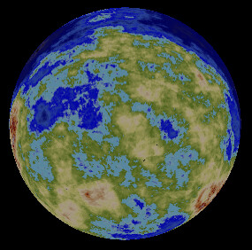
image
I think that may as far as I take it for now.

I really appreciate your help!!

Turn on clamp … er set it to the sampler states dunno if anyone mentioned that.

you might have to create your own state if you want a specific texture filter to go with it.
Like there is pre-existing PointClamp and LinearClamp i think im not sure though.
Technically they are very separate things but they get set in the same place on the shader.