Yah, it’s strange. I think I was just ordering them correctly by luck. It might be just for the first texture but later textures seem to work in any order.
Oh I just noticed something. It might not be important but,
since spriteBatch is drawing inittarget - internally it sets s0 / t0 texture (BaseTexture) to inittarget already.
This means you can probably comment out this line:
//mEffect.Parameters("BaseTexture").SetValue(inittarget)
I’m not sure it would make any difference though.
You are correct, commenting out the line has no impact, so the line was not worthwhile.
One thing still has me slightly baffled, but I’m not sure how far I want to study it. I have two render targets. initTarget is built up of a series of calls to Draw. This sets the background image, draws on fish if necessary, and draws two concentric circles. Those are the items that remain once the masking has been completed.
As the next step, I do the masking, which is what this thread has really been about. However, I notice that the final line of the masking is the call to Draw where the initTarget is drawn on the current RenderTarget (fishTarget). This step puts the two pieces together, the composite background image in initTarget along with the stencil.
It seems to me that I could add the stencil first, and do all the drawing in one pass. Basically, the way I have it now there is the one call to .Draw to put the initTarget in place, but initTarget is just built up via a series of .Draw statements, so I would think that I could move the stencil code prior to all these .Draw statements and it would work the same.
This is not quite the case. It sort of works, but some of the drawing ends up being kind of odd.
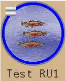
Here’s what it looks like using the two render targets, which is the way I want it to look:
And here’s what happens if I use just a single render target:
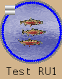
It’s not horrible, but not ideal, either. The circle is drawn as a series of points that make up a circle. Therefore, the circles are really a string of beads. When I use the two RenderTarget approach, the string of beads blend together to make a nice circle. When I use the single RenderTarget approach, something about the stencil is causing the string of beads to resolve into individual points.
I’m curious as to why that is. There would be the slightest performance advantage to using a single RenderTarget, but the performance is excellent already, so I’m inclined to go with the better looking approach. I’d just like to understand why adding the pixel shader to that single RenderTarget and doing the composition and stencil in a single step is causing a change in the way the circles are rendered?
EDIT: Actually, upon studying those images a bit more closely in a paint program, I notice that there are other differences, as well. If one looks closely at the fish tails in the two images, you’ll notice that the bottom of the lower tail, and the top of the upper tail have both been chopped off. Upon studying the zoomed image, quite a bit of the lower tail has been removed, while very little of the upper tail has been. Interestingly, those are the ONLY differences: The circles, the lower part of the bottom tail, and just the tip of the upper part of the top tail.
I think I can understand the string of beads result for the circles a whole lot better than I can understand how parts of the fish tails could have been clipped…except that…if I draw a circle onto the image, it would perfectly chop off those parts of the tails if the circle was drawn at the right height. In other words, it looks as if there was masking done on the fish image with a smaller mask than the one used on the whole image, but perhaps of the same, circular, shape. The argument against that is that the snouts of the fish should also have been impacted if the mask were truly circular, and they have not been. To include all of the jaws, the clipping has to have happened with an ellipse that was slightly elongated.
If you are trying to make a circle per draw on the shader you can actually do that algorithmically as a added on function to your pixel shader i made a method for it somewere ill dig it out in a bit.
currentPixel is the current interpolated position sent in from the vertex shader to the pixel shader
testPosition is the center point about which the circle is to be drawn thats gotta be within the actual drawn screen quads for the draw call.
So these are shader functions you put them before the vertex or pixel shaders of your own so they are compiled first and available.
//---  directly draw lines on the shader.
// boils it down basically to a boolean variable 1.0f is true 0.0f is false.
float4 DrawLine(float2 curpixel, float4 currentColor, float2 a, float2 b, float lineThickness, float4 linecolor)
{
    float2 p = curpixel;
    float t = lineThickness;
    float2 c = b - a;
    float2 n = normalize(float2(-c.y, +c.x)); // normalized cross ab
    float2 i = -(n * dot(n, p - a) * 2.0f); // inflected perp normal
    float dist2line = 1.0f - saturate((i.x * i.x + i.y * i.y) / (t * t)); // distance of point to line.
    float isinbounds = saturate(sign(dot(a - p, a - b) * dot(b - p, b - a) + 0.001f)); // + 0.0001f  determine point is within segment.
    float strength = dist2line * isinbounds;
    return lerp(currentColor, linecolor, strength);
}

//---  directly draw circles on the shader.
// boils it down basically to a boolean variable 1.0f is true 0.0f is false.
float4 DrawCircleAtRadius(float2 curpixel, float4 currentColor, float2 testpos, float radius, float lineSize, float4 linecolor)
{
    float strength = (1.0f - saturate(abs(distance(curpixel, testpos) - (radius - lineSize / 2)) / (lineSize / 2)));
    return lerp(currentColor, linecolor, strength);
}

//---  directly draw points on the shader.
// boils it down basically to a boolean variable 1.0f is true 0.0f is false.
float4 DrawPoint(float2 curpixel, float4 currentColor, float2 testpos, float range, float4 linecolor)
{
    float2 dif = curpixel - testpos;
    float strength = 1.0f - saturate((dif.x * dif.x + dif.y * dif.y) / (range * range));
    return lerp(currentColor, linecolor, strength * strength);
}
in the pixel shader
float4 PsShaderDebugDraw(float4 position : SV_Position, float4 color : COLOR0, float2 texCoord : TEXCOORD0) : COLOR0
{
 // ....

 // display circular radius about midpoint m.
    currentColor = DrawCircleAtRadius(p, currentColor, m, length(c - b) * 0.5f, 3.0f, lineColorYellow);
I made that for this test project the full shader is in there with a game1 that uses it.
1 Like
That’s an interesting approach, I’ll have to think about it.
You would probably have to take a look at the actual pixel shader that is using it to see how i passed positions and stuff from the vs to the ps to be used and how its called and used in the pixel shader
Its basically checking and modifying colors if they fall into the circle radius range from the position specified as the center to draw it from.
It could be fully based on texel positions instead of pixel positions i sort of slopped it together there. but with what your doing it maybe will work better the way it is.
weird dunno why i had to post that as a hyperlink well there you go edited the previous post.