[Resolved...ish] Shader Question

At this point, I’m kind of stumped on a shader issue on which a fair amount has been written. I have a control written in XNA 4.0 that is doing a mask. This was working in 4.0, and is the last item that I have yet to be able to move over to MG3.8. With the amount that has been written about it, I have various code to follow along. For example, I believe my shader code is identical to that found in the first answer in this link:

Of course, that is also XNA, so perhaps that’s part of the problem. My shader code looks like this:

sampler MaskTexture : register(s1) {
    addressU = Clamp;
    addressV = Clamp;
};

//
float MaskLocationX;
float MaskLocationY;
float MaskWidth;
float MaskHeight;
float BaseTextureLocationX;  //This is where your texture is to be drawn
float BaseTextureLocationY;  //texCoord is different, it is the current pixel
float BaseTextureWidth;
float BaseTextureHeight;

float4 PixelShaderFunction(float2 texCoord: TEXCOORD0) : COLOR0
{
    //We need to calculate where in terms of percentage to sample from the MaskTexture
    float maskPixelX = texCoord.x * BaseTextureWidth + BaseTextureLocationX;
    float maskPixelY = texCoord.y * BaseTextureHeight + BaseTextureLocationY;
    float2 maskCoord = float2((maskPixelX - MaskLocationX) / MaskWidth, (maskPixelY - MaskLocationY) / MaskHeight);
    float4 bitMask = tex2D(MaskTexture, maskCoord);

    float4 tex = tex2D(BaseTexture, texCoord);

    //It is a good idea to avoid conditional statements in a pixel shader if you can use math instead.
    return tex * (bitMask.a);
}

technique Technique1
{
    pass Pass1
    {
        // TODO: set renderstates here.
		PixelShader = compile ps_4_0 PixelShaderFunction();
    }
}

The code that uses the shader is here:

		'This line sets the backcolor to the backcolor of the control, which would mean that anything outside the stencil will appear as the background color
		fishTarget.GraphicsDevice.Clear(RUGroupBackColor)
		mSprites.Begin(SpriteSortMode.Immediate, BlendState.AlphaBlend)

		Dim snShrt As Single = shrt
		mEffect.Parameters("MaskWidth").SetValue(snShrt)
		mEffect.Parameters("MaskHeight").SetValue(snShrt)
		mEffect.Parameters("BaseTextureWidth").SetValue(snShrt)
		mEffect.Parameters("BaseTextureHeight").SetValue(snShrt)
		mEffect.Parameters("BaseTexture").SetValue(inittarget)
		mEffect.Parameters("MaskTexture").SetValue(mStencil)
		mEffect.CurrentTechnique.Passes(0).Apply()

		'Merge the initTarget (which has the fish, the RWPB, and the border) into the current.
		mSprites.Draw(inittarget, New Rectangle(0, 0, shrt, shrt), Nothing, Color.White, 0.0, Vector2.Zero, SpriteEffects.None, 0)
		mSprites.End()

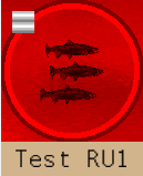
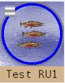
Not much to it, but it’s not doing what I expect, and I’m not quite sure what it IS doing. If I comment out the shader, so that I see the image that is being clipped, it looks like this:

Unclipped

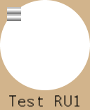
When I add in the shader, I get this:

ShaderInPlace

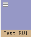
The tan color is the background onto which everything else is drawn. The odd little square of white and gray gets drawn on later, as does the text. What should be showing up is the blue circle from the first picture and everything inside of it, while the perimeter outside the blue circle (actually, outside the faint gray circle bordering the blue circle) should be that background tan color.

I’m not even sure where that color in the second image is coming from.

The stencil is a white circle in a black rectangle of the same size as what is shown. As far as I can tell, it appears to be correct.

Clearly, I’m doing something wrong, and I would assume it’s something simple, but I can’t find it.

Any suggestions?

Thats a screen space square masking function it wont mask a circle in a sprite you draw. That function is masking a square area on the screen.

If your intent is to mask a circular area in a sprite you are drawing in a arbitrary location, on a per sprite basis then it would be something like.

float4 tex = tex2D(BaseTexture, texCoord);
float2 dist = distance (texCoord.xy, float2(0.5f,0.5f); // .5 .5 is the center of the image
float inbounds= saturate(sign(dist - threshold));
// if you are pre-multiplying your alpha and not using non premultiplied you might need to call clip(inbounds) and remove the above saturate.
// blendstate on the graphics device affects if the (alpha) portion of rgba is considered directly.
return tex * inbounds;

were threshold is some distance 0 to 1 in relation to the sprites edges to its center by which to shrink or expand the circle.

if you need something based on a square position like that one seems to do then you can actually just set the scissors rectangle on the graphics device (see jjags reply below) or use a shader.
Note the below forces spritebatch to use the vertex shader in the .fx as well you could probably make it much more efficient it was a test example though.

The mask is a black square with the center chopped out:

128x128Hole

Everything that is black should be removed, while everything that is white should remain unchanged. I suppose this means multiplying the alpha values for each corresponding pixel. Both the source and the target are rectangles. In my particular test case, they happen to be rectangles of the same size (128x128), but that’s pretty much irrelevant, they are proportional.

So, while the goal is to mask off a circle, the mask isn’t a circle. In fact, it can’t be, because I have a torus that I’ll need to mask next. I’m not sure that I can describe a torus mathematically the way a circle can be described. I certainly couldn’t describe an arbitrary shape.

I’d try this:

sampler MaskSamp : register(s1) {
    Texture    = <MaskTex>;  // << need to pass to this here for anything above s0
    AddressU = clamp;
    AddressV = clamp;
};
//...
struct VSOutput{
	float4 pos : SV_POSITION;
	float4 col : COLOR0;
	float2 uv  : TEXCOORD0;
};
//... 
float4 PixelShaderFunction(VSOutput input) : COLOR
{
    float2 texCoord = input.uv;
//...
float4 bitMask = tex2D(MaskSamp, maskCoord);
//...

mEffect.Parameters("MaskTex").SetValue(mStencil)

2 things I watch for is how texture is passed in and received and if the input in the pixel shader matches up to the output of the vertex shader (like the default one for spriteBatch).

I guess my question is shifting to find a good way to debug shader effects.

I’ve been studying the code I posted in the first example and trying a series of different tests. The results have been suggestive, but hard to see quite what is going on. The code I originally posted seems pretty much right for two reasons:

  1. It was working for a decade under XNA 4.0.
  2. It matches something I found online exactly.

So, if it’s off, it’s not far off. That gave me a starting point to work from. With no other approach to studying it that I am aware of, I wrote a series of pixel shaders called by a variety of different Techniques, so that I could easily switch from one shader to the next.

In the first test, I simply wanted to see what the texture was, so what I wrote was essentially this:

float4 PSFive(float2 texCoord: TEXCOORD0) : COLOR0
{
    float4 tex = tex2D(BaseTexture, texCoord);
    return  tex; //
}

I felt that this would just return the base texture. What it resulted in was the second picture in my first post (just a blank, purplish, square).

I then decided to see what the mask looked like, so I wrote a shader that did this:

float4 PSSix(float2 texCoord: TEXCOORD0) : COLOR0
{
    float maskPixelX = texCoord.y * BaseTextureWidth + BaseTextureLocationX;
    float maskPixelY = texCoord.x * BaseTextureHeight + BaseTextureLocationY;
    float2 maskCoord = float2((maskPixelX - MaskLocationX) / MaskWidth, (maskPixelY - MaskLocationY) / MaskHeight);
    float4 bitMask = tex2D(MaskTexture, maskCoord);
    return  (bitMask.a); //
}

I was thinking that this would return the mask texture itself. After all, there isn’t any scaling going on in this case. Both the base and mask textures should be 128x128, so I would be expecting that this:

float4 bitMask = tex2D(MaskTexture, maskCoord);

would return a pixel in the mask that was unscaled in any way. That isn’t the case, though, as the result was pure white. I tried a few variations on that, but the result was always consistent. The A value for every pixel is 1.

So, why is that? I’m not sure, and that’s where it gets frustrating. This is just math. I make plenty of math errors, so I’m pretty much used to debugging math errors, but in this case I’m not sure how to get my hands on the intermediate values. That function creates a series of intermediate values. I feel that, if I could see what was in those intermediate values (maskPixelX,maskPixelY, etc.) I’d better understand what the function was doing and why it was returning what it’s returning.

Any texture after the first one, needs to be passed as a parameter into a format similar to what I suggested. This can be done right after loading the effect. fx.Parameters[“MaskTexture”].SetValue(MaskTexture); - but you’ll need to modify the sampler in the way I mentioned above.
Also I’m pretty sure the pixel shader input must match exactly to the vertex shader output (order too).
Probably everything else about your code will be identical to before and should work the same.

There is no vertex shader, so matching the output isn’t really a thing. That appears to be fine, too, as I was able to use just the pixel shader to color the image (set it to a solid color).

I’ll try the texture. In the original code, I didn’t pass either texture in. Instead, I set two textures in the graphics device:

GraphicalDevice.Textures(0) = inittarget
GraphicalDevice.Textures(1) = mStencil

where the initarget is the background texture. This results in a tan rectangle in most of the tests I ran. Since tan would be the default background color, in this case, I would assume that pretty much means that no shading happened at all. That was the code that worked in XNA4.0, so it may have been a difference between DX9 and DX11.

The change between your sampler MaskSamp and mine had no impact.

One thing I noted was that my mask wasn’t really a mask at all. I was working with the A value, but my PNG was using black for the transparent areas, with an alpha value of 255, so ALL pixels should have been drawn. There was no masking going on at all. There are a couple ways I could have fixed that, but what I ended up doing was just creating a new mask where the transparent parts were actually transparent. The alternative would be to multiply by R, G, or B, rather than A, since those would all be 0 if black was the transparent area.

Swapping to the transparent image had no impact, either. At this point, I’m pretty much baffled. This is the pixel shader I’m currently working with in an attempt to get just the mask to draw on the screen:

float4 PSSix(float2 texCoord: TEXCOORD0) : COLOR0
{
    float4 bitMask = tex2D(MaskTexture, texCoord);
    return  float4(bitMask.a,0,0,bitMask.a); //
}

All that does is results in a red rectangle, which indicates, to me, that for every texCoord, the color returned from the MaskTexture is (?,?,?,1), where I neither know nor care what the RGB portion is.

My understanding of the tex2D method is that it gets the value from the texCoord of the mask texture. In this case, the mask is 128x128, with a bunch of it being transparent (a = 0) while most is opaque (a=1). Therefore, if I am understanding tex2D correctly, for this shader to be producing a solid red rectangle of size 128x128 (the size of the area being drawn), either texCoord would have to always be the same thing (a point somewhere in the middle of the texture), or the texture being sampled is not what I thought it was.

I guess the next step is to determine which of those two scenarios is the right one.

SpriteEffect.fx in monogame contains the default vertex shader using the format I mentioned. Gfx card / pipeline won’t do pixel shading without one because it needs to know what to do with the vertices first. It may work but to be safe, I’d probably try to match the output data to the input data. I always see everyone doing that.

GraphicalDevice.Textures(1) = mStencil

Passing Texture(0) [s0] will work but passing textures 1,2,3,4,5… will not work this way. At least I’ve never seen it happen yet. Ppl always pass these textures using something like: fx.Parameters[“MaskTexture”].SetValue(MaskTexture);
And then using the sampler style I mentioned before.

Also you may want to check your Blendstate and ensure it’s matched to the texture build in Content. ie: If Content has the texture set to Premultiply alpha, then you’d use AlphaBlend otherwise it would be NonPremultiplied. Sometimes one doesn’t match and it can mess things up a bit - in this case I’d say that likely isn’t the problem.

1 Like

I believe you need to define both a texture and a sampler2D in your shader and then use the sampler when you call tex2D.

texture MaskTexture: register(t1);
sampler2D MaskSampler : register(s1)
{
    Texture = (MaskTexture);
    MipFilter = None;
    AddressU = Clamp;
    AddressV = Clamp;
};

float4 PSSix(float2 texCoord: TEXCOORD0) : COLOR0
{
    float4 bitMask = tex2D(MaskSampler, texCoord);
    return  float4(bitMask.a,0,0,bitMask.a); //
}

@Zarquon: That change had no noticeable impact. I believe it is doing roughly the same thing in a slightly more verbose fashion, but that’s not a bad thing.

@AlienScribble: Using the VertexShader argument got me considerably closer. I’m now seeing the background, but the mask is not masking anything. There are several pieces I need to check on that to see what is going on, but at least I’m now seeing something recognizable, which makes it far easier to understand.

Changing from AlphaBlend to NonPremultiplied had no impact.

For test purposes, this was the PixelShader I was using, which I expected to just show the bitmask:

float4 PSSix(VSOutput input) : COLOR0
{
   float4 bitMask = tex2D(MaskSampler, input.uv);
   return  float4(bitMask.b,0,0,1); //
}

The result was this:
RedOverlay

What this is showing is the background (the fish, the slightly wavy appearance behind the fish, and the circle). The grey scale square, the text, and the tan are all drawn afterwards.

If you look at the shader, all I’m doing is sampling the mask, which is either a transparent and white, or black and white image (I have both, and have tried both, with the same result). Instead of using the A value, I left that at 1, and used the B value (in place of the R, which is why the whole thing looks red). Note that the red color is not bright red. That B value is not 1. I have a different example where I do use 1 rather than the B value, and it is a clearly different, brighter red.

So, what I’m seeing is that the entire image has a solid, semi-transparent, layer on top of the correct underlying layer. Using the VertexShader output as an argument got the proper background showing, which is certainly a step in the right direction, but the output is also clearly blending in the same value for all pixels, not a sample taken from the texture, as far as I can see.

I’m clearly not understanding something, as I would expect that pixel shader to simply return a variation on the mask itself (either transparent and red or black and red, depending on the mask used). I’m largely ignoring the input, aside from using it to identify a point in the mask texture, yet I’m seeing a semi-transparent overlay on the background.

Yah, that’s odd.
The shader seems fine so I’d try reducing other possible causes.
I’m guessing you already tried changing this:
GraphicalDevice.Textures(1) = mStencil
to this(?):
fx.Parameters[“MaskTexture”].SetValue(mStencil);
And you said it’s not being processed as a premultiplied texture in the Content builder and you’re using non-premultiplied blendstate… so I’m wondering how stuff around the draw part of your code looks. Maybe there’s some other clues there?

I’m back to this, with some semi-new information. So, just to reiterate, this is the drawing code:

		GraphicalDevice.SetRenderTarget(fishTarget)
		'This line sets the backcolor to the backcolor of the control, which would mean that anything outside the stencil will appear as the background color
		fishTarget.GraphicsDevice.Clear(RUGroupBackColor)
		mSprites.Begin(SpriteSortMode.Immediate, BlendState.AlphaBlend)

		Dim useEffect = mEffect
		Dim snShrt As Single = shrt
		useEffect.Parameters("MaskWidth").SetValue(snShrt)
		useEffect.Parameters("MaskHeight").SetValue(snShrt)
		useEffect.Parameters("BaseTextureWidth").SetValue(snShrt)
		useEffect.Parameters("BaseTextureHeight").SetValue(snShrt)
		useEffect.Parameters("BaseTexture").SetValue(initTarget)
		useEffect.Parameters("MaskTexture").SetValue(mStencil)
		useEffect.CurrentTechnique = useEffect.Techniques("Technique1")
		useEffect.CurrentTechnique.Passes(0).Apply()

		'Merge the initTarget (which has the fish, the RWPB, and the border) into the current.
		mSprites.Draw(inittarget, New Rectangle(0, 0, shrt, shrt), Nothing, Color.White, 0.0, Vector2.Zero, SpriteEffects.None, 0)
		mSprites.End()

What I’m trying to do as a test is to SOLELY draw the stencil, thereby ignoring the underlying texture. To do this, I’m using this very simple technique:

float4 PSSix(VSOutput input) : COLOR0
{
   float4 bitMask = tex2D(MaskSampler, input.uv);
   return  float4(bitMask.r,bitMask.g,bitMask.b,bitMask.a); //That's a slow way of returning just the pixel from the mask.
}

Essentially, I’m ignoring the input aside from using the coordinates in the call to tex2D. What I
am returning is just the float4 (poorly, as the comment notes).

I also have this in the file (along with 5 other pixel shaders so that I can try different things without recompiling the effect):


texture MaskTexture : register(t1);
sampler2D BaseTexture : register(s0);
sampler2D MaskSampler : register(s1) {
    Texture    = <MaskTexture>;
    addressU = Clamp;
    addressV = Clamp;
};

struct VSOutput{
	float4 pos : SV_POSITION;
	float4 col : COLOR0;
	float2 uv  : TEXCOORD0;
};

As far as I can see, what this SHOULD be doing is getting the pixel from the MaskSampler at the uv coordinates supplied. I then went to look at the stencil itself as a Texture2d (as opposed to the png that it loads from), and it looks pretty good. Not ideal, as some anti-aliasing could be less than what I want, but there are large swaths of black pixels (0,0,0,0) and white pixels (255,255,255,255).

What is coming out when I use the code shown is whatever is in the background (initTarget).

I kind of think that I understand why, because the final line in the code is this:

mSprites.Draw(initTarget, New Rectangle(0, 0, shrt, shrt), Nothing, Color.White, 0.0, Vector2.Zero, SpriteEffects.None, 0)

That will draw whatever is in initTarget. I was assuming that the effect was altering what was in initTarget via the technique. That doesn’t appear to be the case. If I comment out that line, then I get my standard tan background color, which would suggest that whatever the effect is doing, it is not changing initTarget, or whatever changes it is making are not being displayed.

Basically, that final line seems to be everything that is done in the code block. If it is there, then the render target gets whatever was in initTarget. If the line isn’t there then the render target gets nothing. Commenting out all the code that deals with the effect has the exact same result. It is as if the effect was doing nothing at all.

The only argument against that is that if I use a technique that simply returns a red pixel as the pixel shader, I get a solid red square, which means that the technique IS doing something, it just doesn’t do what I’d expect. In fact, it kind of acts like the MaskTexture is being set to the background image, not to the stencil image.

I realize this is long, but I’ve been studying this over and over and there’s a lot of data. Any suggestions?

Considering it optimizes out what isn’t used. Maybe it also does something weird where it wants to make use of slots in order of appearance depending on usage. As an experiment, I’d try commenting BaseTexture s0 if it’s not used (at the moment), and try changing Mask stuff to s0, t0 and see if it samples as expected. Another experiment to try: return bitmask * 0.96 + tex2D(BaseTexture, input.uv) * 0.04
If the experiment works, it’ll show 96% of the bitmask result and hint(4%) that the basetexture is being sampled. If this happens, then you know that not using the BaseTexture has something to do with it whatever weirdness is going on with where it’s sampling from.
At least it’s a way to figure out what might be happening anyway. ;p

You could take a look at this maybe it will help.

Despite the name of the post this is just a shader and game1

I made this as a example to show how one could do a 2d version of a planet scrolling.
Or a scrolling background behind say a window in 2d.
With transparency and color blending thrown in as well ect.

1 Like

@AlienScribble: Some progress, I believe, but so many tests that I’m not quite sure of the outcome. The key point was that I didn’t quite follow your first suggestion. I commented out BaseTexture, changed mask to s0, but neglected to change t1 to t0. The result was no change. I then…well, then I tried the second suggestion which resulted in no change. No change just means that the whole rectangle was the background image with a circle on it plus fish, as seen earlier.

I then noticed my oversight and repeated the first suggestion while changing t1 to t0. Using this PS technique:

float4 PSSix(VSOutput input) : COLOR0
{
   float4 bitMask = tex2D(MaskSampler, input.uv);
   return  float4(bitMask.r,bitMask.g,bitMask.b,bitMask.a); //That's a slow way of returning just the pixel from the mask.
}

The result was this:
PartialSuccess

That’s the mask, and looking right. No background image, but with that technique, which ignored the background image, there shouldn’t have been a background image. So, progress.

I felt that the next thing to try was a brute force approach to the background, which was this:

float4 PSFive(VSOutput input) : COLOR0
{
     float4 bitMask = tex2D(MaskSampler, input.uv);
     float4 tex = tex2D(BaseTexture, input.uv);
    return  float4(tex.r,tex.g,tex.b,bitMask.a); 
}

There’s no real sampling there, but in the test case, the images are the same size as the target, so it’s a 1:1 mapping. The result was the same as the previous image, except the inside of the circle is flat black.

One other point is that while doing all this, I had changed t0 back to t1 while using this latter technique. That resulted in a solid black square (no masking). I noticed that mistake and turned t1 back to t0, which resulted in the black circle.

From this, I take it that I need to declare the variables like so:

texture MaskTexture : register(t0);
sampler2D BaseTexture : register(s0);
sampler2D MaskSampler : register(s1) {
    Texture    = <MaskTexture>;
    addressU = Clamp;
    addressV = Clamp;
};

I can’t say why, though. Clipping happens if MaskTexture is in t0, but not in t1. The PSSix function is just using the sampler, and it looks right, but switching to PSFive, which is very similar to PSSix, except that it uses the base rather than the mask for the RGB values, all I get is black, which suggests that the base is empty.

At this point, I’m using those registers without understanding them, but they seem to hold the key.

@willmotil: Having looked at your example, I’m even more convinced that the key to this problem is the fact that I am throwing this part of my effect file:


texture MaskTexture : register(t0);
sampler2D BaseTexture : register(s0);
sampler2D MaskSampler : register(s1) {
    Texture    = <MaskTexture>;
    addressU = Clamp;
    addressV = Clamp;
};

at the problem without understanding what that does. I believe that the pixel shader function is reasonably straightforward, but I’m not setting up the textures in the proper fashion. I see that you did very similar things (you used Wrap rather than Clamp, but I think I understand that part), but not quite the same.

I’m looking for a better understanding of what those few lines of code are doing. I have a couple books on the way that might help, but any explanation/insight would be valuable, at this point. That’s most likely where my issues lie, and I’m throwing code at it blindly, at this point.

Ah, I forgot something. I think someone found out that for some weird reason, the order that you sample in the pixel shader should start with s0’s sampler. I think I’ve never noticed it myself because coincidentally the order has always matched up for me.
Btw - you should be able to do like this (I’ve never found a need for the Texture and ‘T’ register stuff):

sampler2D BaseSampler : register(s0) {
    Texture = <Texture>; // this will be set by spritebatch
}
sampler2D MaskSampler : register(s1) {
    Texture = <MaskTexture>; // passed in
    addressU = Clamp;  // resample at the edge of the texture if trying to sample past the edge
    addressV = Clamp;  // if using Wrap, it'll start sampling from the other side, if mirror it'll go backward
};

The part I’m about to show is actually what I’m talking about.
For whatever reason I think s0 needs to be sampled first and then s1:
So instead of this:

float4 bitMask = tex2D(MaskSampler, input.uv);
float4 tex = tex2D(BaseSampler, input.uv);

//You might need to order them like this instead (I know it doesn't make sense):

float4 tex = tex2D(BaseSampler, input.uv);
float4 bitMask = tex2D(MaskSampler, input.uv);

I think it might be an s0 thing since I’ve not noticed the order being important with other textures.
Like I said, it’s never happened to me before but I always end up sample s0 first so that may be why.
I have heard of someone noticing this before.
Maybe someone can confirm this?

1 Like

I wrote a very lengthy reply before you wrote this. I was methodically testing a variety of different changes and getting a fairly comprehensive picture of the shape of failure…and then it mostly worked. I knew that I was not using the right Technique, as I had six different Techniques all with slight changes. Once I switched to the right one, it worked completely.

So, what I found was that this was what was essential:

#define PS_SHADERMODEL ps_4_0_level_9_1

texture MaskTexture : register(t0);
sampler2D BaseTexture : register(s0);
sampler2D MaskSampler : register(s1) {
    Texture    = <MaskTexture>;
    addressU = Clamp;
    addressV = Clamp;
};

struct VSOutput{
	float4 pos : SV_POSITION;
	float4 col : COLOR0;
	float2 uv  : TEXCOORD0;
};

//
float SomeValue;
float MaskLocationX;
float MaskLocationY;
float MaskWidth;
float MaskHeight;
float BaseTextureLocationX;  //This is where your texture is to be drawn
float BaseTextureLocationY;  //texCoord is different, it is the current pixel
float BaseTextureWidth;
float BaseTextureHeight;

float4 PixelShaderFunction(VSOutput input) : COLOR0
{
    //We need to calculate where in terms of percentage to sample from the MaskTexture
    float maskPixelX =  input.uv.x * BaseTextureWidth + BaseTextureLocationX;
    float maskPixelY =  input.uv.y * BaseTextureHeight + BaseTextureLocationY;
    float2 maskCoord = float2((maskPixelX - MaskLocationX) / MaskWidth, (maskPixelY - MaskLocationY) / MaskHeight);
    float4 bitMask = tex2D(MaskSampler, maskCoord);

    float4 tex = tex2D(BaseTexture, input.uv);

    //It is a good idea to avoid conditional statements in a pixel shader if you can use math instead.
    return  tex * (bitMask.a); //
}

I’m still baffled by the line putting the texture into t0. If that line is commented out, then no masking happens at all. In fact, it’s as if the effect was doing nothing whatsoever. However, the code runs, and one line of that code is telling:

useEffect.Parameters("MaskTexture").SetValue(mStencil)

If you comment out a variable that is used, then there will be no such parameter, and attempting to set a parameter that doesn’t exist will throw an exception, as it should. So, the fact that this runs when t0 is commented out is significant because it means that MaskTexture is still defined, which it is, as part of the MaskSampler. Also, note that MaskTexture is not used in the Technique, only MaskSampler (which contains MaskTexture) is used in the Technique.

So, putting the stencil into t0 is not necessary for the parameter to exist, but it IS necessary to get the effect to work. Without that step, it does nothing at all. That would suggest that it is MaskSampler that isn’t necessary, but ONLY MaskSampler is referenced in the shader, so the effect wouldn’t even compile without MaskSampler. Therefore, t0 is essential for some reason, though it isn’t clear why it should be.

Comparing back to my very first post, which contained my old XNA 4.0 code, I note that BaseTexture was never declared in that shader. That shouldn’t compile, and indeed it does not. It DID work under XNA 4.0, though, so apparently there was some kind of implicit declaration going on back then.

It also looks like a bad shader results in no shader at all. If it compiles, but doesn’t do anything good, then you get no effect, which in this case means that there is no masking at all. If this is true, then it suggests that commenting out t0 causes some kind of internal problem, possibly with setting the texture in MaskSampler. I can still pass in the stencil as a parameter, and the parameter is still there, but since it doesn’t go through t0…what? It isn’t real?

I don’t believe this is the only question, either. Commenting out all the effect code results in just drawing the background, which makes sense, because a call to .Draw with the background is the final line in the Sprite composition (shown in the original post). If the effect is commented out, then all that is happening is drawing an existing image onto a specific render target, and that’s a pretty simple process.

However, I was also able to get nothing to draw at all. At the moment, I can’t recreate those conditions.

The key points I have learned from this thread are:

  1. Even though I don’t have a vertex sampler, I still need to pass in the results of the vertex sampler, which indicates that MG is using the default sampler when no other is supplied.

  2. I have to put the stencil into t0, even though it is then passed into a sampler that is in s1. I have no idea why this is, but it appears to be essential.

  3. If the effect compiles, that doesn’t mean that it will work. This may indicate that internal exceptions due to invalid or incorrect parameters are quietly being swallowed.

Interesting. Perhaps setting t0 is fixing whatever strange thing happens if you don’t sample the base texture first? So I’m guessing maybe base texture is switched into t1 since t0 is already taken?
I never actually use the t0,t1 stuff but I think I always sample from base texture first in pixel shader (s0).
What happens if you comment out the line: texture MaskTexture : register(t0);
And then in the pixel shader:
Place this line as the very first line before any other sampling:
float4 tex = tex2D(BaseTexture, input.uv);

1 Like

If you look back to what I think is post #16, you will see PSFive, which is almost what you are describing, except that I take from the MaskSampler before the BaseTexture.

If I use that PSFive sampler with t0 included I get the correct output, except that the area that should be transparent is white.

If I use PSFive as shown with t0 commented out I get no masking at all. The background image is shown without any stencil.

If I then swap the lines in PSFive such that I get tex prior to bitMask, I’m back to getting the correct output with the white areas where it should be transparent.

float4 PSFive(VSOutput input) : COLOR0
{
    float4 tex = tex2D(BaseTexture, input.uv);     
    float4 bitMask = tex2D(MaskSampler, input.uv);
     
    return  tex * (bitMask.a);
}

If I then fix the return line:

return tex * (bitMask.a);

I get the correct output with t0 no longer in use.

The final test is to uncomment t0. This resulted in the correct output, as well, so with tex and bitMask in the proper order (tex coming first), I get the correct output regardless of whether t0 is used or not.

Therefore, you are clearly on to something. You are correct, the order of setting tex vs bitMask makes all the difference, and t0 only makes a difference if bitMask is set before tex. So, what does that suggest? I can clearly get rid of t0 entirely, which is nice, as it simplifies the code, but what exactly was t0 doing when tex and bitMask were being set in the wrong order? Why does the order matter?

It suggests to me that variables in HLSL are a much looser thing than in languages I am used to. The order of setting two independent variables shouldn’t matter, but that test shows that it clearly does. That seems to suggest that the variables BaseTexture and MaskSampler are entwined in some way. Also, if the variables are set in opposite order (s1 is sampled before s0), then adding t0 ‘fixes’ the problem, but if the variables are set in correct order (s0 is sampled before s1), then t0 has no impact whatsoever.

I’d say I learned something, but I sure can’t say what it is that I learned.

1 Like