Wind Shader

It is hard to get into shader programming. Can anyone recommend me a book or site? I did search for hours and the only thing I got working was this
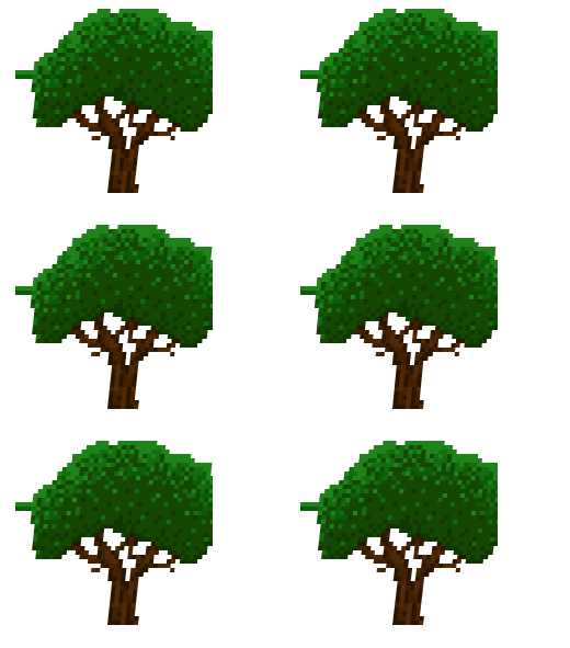
However, the image crops of. I guess, because the texCoords did change and thus the tex2d() can’t read the corresponding pixel anymore. How can I avoid the image crop and the weired extension on the left side? My source so far.

#if OPENGL
	#define SV_POSITION POSITION
	#define VS_SHADERMODEL vs_3_0
	#define PS_SHADERMODEL ps_3_0
#else
	#define VS_SHADERMODEL vs_4_0_level_9_1
	#define PS_SHADERMODEL ps_4_0_level_9_1
#endif

Texture2D SpriteTexture;
sampler2D SpriteTextureSampler = sampler_state
{
	Texture = <SpriteTexture>;
};

float4x4 projectionMatrix;
float4x4 viewMatrix;

float gameTime = 1.0;
float bendEnd = 0.5;
float minValue = 0.1;
float strength = 0.005;

struct PixelShaderOutput
{
	float4 Color: COLOR0;
};

struct VertexShaderOutput
{
	float4 Position : SV_POSITION;
	float2 TexCoord : TEXCOORD0;
	float4 Color: COLOR0;
};

VertexShaderOutput VertexShaderLogic(float4 position : SV_POSITION, float4 color : COLOR0, float2 texCoord : TEXCOORD0)
{
	VertexShaderOutput output = (VertexShaderOutput)0;

	output.Position = mul(position, viewMatrix);
	output.Position = mul(output.Position, projectionMatrix);
	output.TexCoord = texCoord;
	output.Color = color;

	if (output.TexCoord.y < bendEnd)
		output.TexCoord.x += minValue + sin(gameTime) * strength;

	return output;
}

PixelShaderOutput PixelShaderFunction(VertexShaderOutput input) : COLOR0
{
	PixelShaderOutput output = (PixelShaderOutput)0;

	output.Color = tex2D(SpriteTextureSampler, input.TexCoord) * input.Color;

	return output;
}

float nrand(float2 uv)
{
	return frac(sin(dot(uv, float2(12.9898, 78.233))) * 43758.5453);
}

technique SpriteDrawing
{
	pass P0
	{
		VertexShader = compile VS_SHADERMODEL VertexShaderLogic();
		PixelShader = compile PS_SHADERMODEL PixelShaderFunction();
	}
};
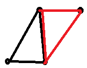
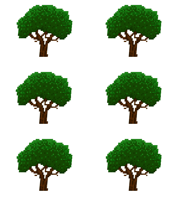
Your sprite is a rectangle created by 4 corner points. No matter how you change the texture coordinates, you can never draw outside of this rectangular area. This is why the image crops, you are trying to draw outside of your sprite-rectangle. You can solve this by changing the position of the corner points instead of changing the texture coordinates.
Try this instead:

VertexShaderOutput VertexShaderLogic(float4 position : SV_POSITION, float4 color : COLOR0, float2 texCoord : TEXCOORD0)
{
	VertexShaderOutput output = (VertexShaderOutput)0;

        output.Position = position;
	if (texCoord.y < bendEnd)
		output.Position.x += minValue + sin(gameTime) * strength;

	output.Position = mul(output.Position, viewMatrix);
	output.Position = mul(output.Position, projectionMatrix);
	output.TexCoord = texCoord;
	output.Color = color;

	return output;
}

Ok, that seems to work… kinda. However, the vertices will be moved nethertheless. The Position isn’t correlated with the texCoord (as far as I interpret the concept)

I’m not exactly sure what you mean. The “bending strength” will be different in my version compared to yours, because changing position by 1 unit is different from changing texcoords by 1 unit. You should be able to get the same results though by adjusting the minValue and strength parameters.

As far as I remember for CG, a Texture2D is made up of 2 triangles. Thus 6 vertices. Hence, if I shift (lets say at y = 0) the x coordinate value, I only modify 2 out of 6 vertices. The result should look like this:

And this is exactly the result I am receiving.

How is that gif I’m looking at not exactly what you were trying to achieve? Looks like your previous gif, but without the problems you wanted to get rid of.

Most of the time people use indexed drawing, in which case you can share the same vertex between multiple triangles. I’m not sure how SpriteBatch is doing it, but my guess is that there are only 4 vertices per sprite.
But even if it’s 6 vertices, it doesn’t make a difference, you would be shifting 3 vertices in this case.

I try to achieve to only bend the top part of the tree. Hence, the trunk should be stable. But it is moving as well.
But with 4 (or 6, doesn’t matter actually) vertices the task is not achievable. I would require a Texture2D with more than 4 vertices.

In other words, the line

if (texCoord.y < bendEnd)

has zero effect. The result equals the same with following if statement

if (texCoord.y < 1)

The only thing this if statement consider is, that the vertices on the bottom (y = 1) won’t move at all. Thats is it. And that is what you see in the .gif

Can you recommend me an other way to achieve this kind of effect with a shader?

Ahh ok, now I get it.
There’s basically two options:

  • use more vertices: This means you have to ditch SpriteBatch and generate your own geometry. Custom geometry generation is not that hard to do.
  • use your original texture-shifting method, but do it in the pixel shader instead of the vertex shader. That way the texture shift can be computed per pixel instead of per vertex. The crop problem could be solved by giving your sprites some extra space along the borders. You can provide this extra space by “scaling the texture towards the center”, if that makes sense

hmm. That makes sense to me. I think I will go with your first recommendation and generate my own mesh. I don’t like the idea of scaling and also the wind logic will be complex as well. (The lower the y axis, the higher the x shift) In terms of performance I have to do some case studies.

However, thank you very much :slight_smile: Hopefully this was my last question :stuck_out_tongue:

You could interpolate it with a polynominal positionally but you would need to pass quite a bit of extra data. You would also need to do quite a bit of complicated calculations on the shader probably to hard to explain without taking a lot of time.

You are probably going to need to do it to a mesh as well at least for anything that needs detail.

You are probably going to have to implement something like this either for calculating your mesh vertices or on the shader to displace the pixel or texel positions either way.

If you draw points on a line going up down from A to C in increments of time that range from 0 to 1 with the below function were the X value of B varys off the center of the line (which initially is half way between A and C (a+c)/2 = b) you get a curve. If you then take that b value and keep it on the line and then instead vary the X position of C you would see that you get the bending curvature that your tree desires.
Because this is a 3d function you only need to use the x and y and this function allows for variations in either dimension the z coordinate in all cases can just be set to zero. You can then see this can be used to create vertices that are morphed which you will need for a mesh.

This is a simple version i wrote a long time ago it doesn’t do any weighting the basis function is set as is but its simple. A robust version and even this is probably enough to write a whole blog on because its just hard to explain and non trivial.

The technique you are asking about falls under the terminology of polynomials, bezier, nurbs, in general spline surface algorithms.
1) basics
2) here some code
3) nurbs at the extreme end

       /// <summary>
        /// what it says
        /// </summary>
        public static Vector3 GetPointAtTimeOn2ndDegreePolynominalCurve(Vector3 A, Vector3 B, Vector3 C, float t)
        {
            double i = 1.0f - t;
            float plotX = 0; float plotY = 0; float plotZ = 0;
            //
            plotX = (float)(
                A.X * 1 * (i * i) +
                B.X * 2 * (i * t) +
                C.X * 1 * (t * t)
                );
            plotY = (float)(
                A.Y * 1 * (i * i) +
                B.Y * 2 * (i * t) +
                C.Y * 1 * (t * t)
                );
            plotZ = (float)(
                A.Z * 1 * (i * i) +
                B.Z * 2 * (i * t) +
                C.Z * 1 * (t * t)
                );
            return new Vector3(plotX, plotY, plotZ);
        }

Basically for a quad you need to pass at least a additional 9 control points that are offset around the quad that represent the morphing you want to occur the vertices are found from this.

the function acts as timing function found from the x y positional difference from the start of the quad to the current pixel in relation to the end of the quad that is then used to find the proportional position on the morphed set of 9 points which is then run thru the function to find the current displaced pixel vertice or texel position.

This is basically one order down from a bezier curve basically what you need to do is spline your image.

It wont be very fast either unless you do it with with vertices like a make a animated mesh to do it.

I have a mesh class here that will save some time if you are commited to this.
Mesh Class generates mesh vertices from point arrays

I have different proposal:
Stick with doing it in pixel shader (original idea by moving vertices was fine, until you mentioned you want only specific parts to move). Leave blank space around texture to ensure enough space for wind (clip at the end of the shader to reduce fillrate cost). Use additional texture that will define how how much are given parts rigid, so you can have trunk to be very solid, branches to be affected slightly and crow of the tree to move a lot. Similiar approach is used when dealing with 3D vegetation, it’s just vertex color to be used instead of texture. (as example in 3d case https://twitter.com/Moirai14895389/status/1065766925693870080)

Ya thats a pretty good idea.

To build on that, you could even just make a bunch of textures that are used as texel drawing offsets.
like a texture that that has is r for x be like 3 pixels left and add that to the actual current texel position.
A bunch of those each frame could actually make a pretty cool little animation even.
You’ll have to make a pixel shader that takes two textures but thats pretty easy.

Generating that for this could probably be handled by hand drawing out the frames.

If you really want to do the mesh vertice thing…
I was digging thru my folders i still have a old NURBS class i made and a couple helper classes for it. That will generate any meshes you might need in any way you want them. It’s so damn sloppy and ugly i cringe to give it out but it’ll work. It will generate up to as much detail as you like input or output wise, it’ll generate 3d surfaces if you wanted but can easily generate distorted meshes.
Or you could use it i suppose to even generate distorted images as discussed above if you cleaned it up a bit.